Download

1 / 10
100 likes | 110 Vues
Study testing internal relative humidity of concrete slabs on metal decking to validate a proposed test depth formula. Includes probe insertion study on RH sensor measurements. Test setup and factors influencing RH measurements explored in detail.

E N D
ASTM Committee F06 F2170 In-situ RH Test Depth Study on Metal Decking (Round II) F2170 Probe Insertion Study Version 1.2 - May 3, 2016 Study Location: American Engineering Testing – St. Paul, MN Test Date & Time: TBA
F2170 In-situ RH Test Depth Study on Metal Decking Objective: Currently when testing the internal relative humidity (RH) of a concrete slab on corrugated (fluted) metal decking, tests are taken at 40% of the deepest section of the slab. Without the use of specialized depth sensing equipment it is challenge for most who perform in-situ relative humidity tests in slabs on metal decking to ensure that the tests are being performed in the deepest portion of the concrete. A formula for establishing an average test depth is being proposed for inclusion in the F2170 test method such that it would no longer be necessary to ensure that tests were conducted in the deepest portion of a slab on metal deck. The following test program is intended to help determine if the proposed formula can be validated.
F2170 In-situ RH Test Depth Study on Metal Decking Photos of new test panel: New SlabFormwork Normal Weight Concrete Placed February 24, 2016
New Test Slab: Exposed width 32 -3/4” Exposed length 7’-4” Vulcraft VLI 3” Decking Slab: Normal Weight w/c 0.45 Aluminum tape 36 ” 32 -3/4” Formwork Crete Claw 3.25” 3” 6.25” 2 x 8 cut to 6.25” ¾” plywood 1.5” 12” 12” 12” 1.5”
Test Setup: Test RH Level c: 85% ( Not to scale ) Proposed Average Depth Formula: Depth of thinnest section (3.25”) + ½ depth of flute (3.0”) x 40% = ½ of 3.0” = 1.5” + 3.25” = 4.75” X 40% = 1.9” Tests @ 40% of 6.25” = 2.5” Formula tests: 1.9” 2.5” Aluminum tape 3.25” 6.25” 3” 1.5” 12” 12” 12” 1.5” 36 ”
F2170 Probe Insertion Study Objective: Currently the F2170 test method permits one to insert the probe immediately following insertion of the hole liner into the drilled hole, or to wait the specified equilibrium period, insert the probe and record the measurement when the drift does not exceed 1% in 5 minutes. Observations made by a number of experienced testing technicians, and several equipment manufacturers suggest that RH measurements are consistently higher when the probe is inserted immediately after the liner is installed, and left in for the entire test period as compared to inserting the probe into the liner at the end of the required exposure period and recording a measurement after 1 or 2 hours.
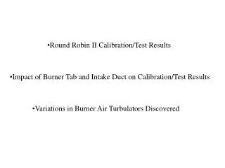
F2170 Probe Insertion Study Factors that affect RH sensor measurements 1. Calibration accuracy (deviation of sensors against a high precision reference) 2. Hysteresis ( Sensor memory) 3. Long term drift ( Affect of sensor age on sensor drift) 4. Creep ( Drift of RH measurement upward in higher RH environments)
F2170 Probe Insertion Study Three sets of each condition 3A, 3B, 3C, 3D, 3E & 3F Probe B New probe New Probe A B C D E F Probe A & B: New probes installed immediately and left in entire time. Measurements recorded at 24, 48 and 72 hours. C: Dummy plugs installed after holes are drilled and lined. Probe from A removed and allowed to stabilize with ambient RH. Probe from A installed after liner has been in 24, 48 and 72 hours. Dummy plug removed, probe inserted and RH measurements taken at 1,2,3 & 4 hours after insertion of probe. D: Dummy plugs installed after holes are drilled and lined. New probe installed after liner has been in 24, 48 and 72 hours. Dummy plug removed, probe inserted and RH measurements taken at 1,2,3 & 4 hours after insertion of probe. E: Probe from B is removed and allowed to stabilize with ambient RH. Probe installed into hole liner E which did not have a dummy plug and has been in place 24, 48 and 72 hours. RH measurements taken at 1,2,3 & 4 hours after insertion of the probe. F: New Probe installed into hole liner F which did not have a dummy plug and has been in place 24, 48 and 72 hours. RH measurements taken at 1,2,3 & 4 & hours after insertion of the probe.
F2170 Probe Insertion Study 12 New Probes & 18 Hole Liners Hole liners with dummy plugs Capped, open hole liners A B C D E F Measurements @ 72 hrs 48 hrs 24 hrs New probes