Shelley Begley Application Development Engineer Agilent Technologies
600 likes | 947 Vues
Electromagnetic Properties of Materials: Characterization at Microwave Frequencies and Beyond. Shelley Begley Application Development Engineer Agilent Technologies. Agenda.

Shelley Begley Application Development Engineer Agilent Technologies
E N D
Presentation Transcript
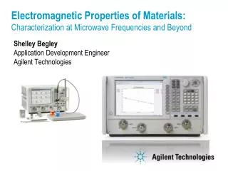
Electromagnetic Properties of Materials: Characterization at Microwave Frequencies and Beyond Shelley BegleyApplication Development EngineerAgilent Technologies
Agenda DefinitionsMeasurement TechniquesParallel Plate Coaxial Probe Transmission Line and Free-Space Resonant Cavity Summary
Definitions Loss Tangent? • Permittivity is a physical quantity that describes how an electric field affects and is affected by a dielectric medium and is determined by the ability of a material to polarize in response to an applied electric field, and thereby to cancel, partially, the field inside the material. Permittivity relates therefore to a material's ability to transmit (or "permit") an electric field…The permittivity of a material is usually given relative to that of vacuum, as a relative permittivity, (also called dielectric constant in some cases)….- Wikipedia Dissipation Factor? Permittivity! Dielectric Constant? Permeability!
Permittivity and Permeability Definitions Permittivity (Dielectric Constant) • interaction of a material in the presence of an external electric field.
Permittivity and Permeability Definitions Permittivity (Dielectric Constant) • interaction of a material in the presence of an external electric field.
Permittivity and Permeability Definitions Permeability Permittivity (Dielectric Constant) • interaction of a material in the presence of an external electric field. interaction of a material in the presence of an external magnetic field.
Permittivity and Permeability Definitions Permeability Permittivity (Dielectric Constant) • interaction of a material in the presence of an external electric field. interaction of a material in the presence of an external magnetic field. Complex but not Constant!
Electromagnetic Field Interaction STORAGE Magnetic Electric Fields Fields Permeability Permittivity MUT STORAGE
Electromagnetic Field Interaction STORAGE Magnetic Electric Fields Fields LOSS Permeability Permittivity MUT STORAGE LOSS
Quality Factor Dissipation Factor Loss Tangent
Water at 20o C 100 10 most energy is lost at 1/t 1 1 10 100 f, GHz Relaxation Constant t • t= Time required for 1/e of an aligned system to return to equilibrium or random state, in seconds.
Measurement Techniques Coaxial Probe Parallel Plate Transmission Line including Free Space Resonant Cavity
Which Technique is Best? It Depends…
Which Technique is Best? It Depends… on • Frequency of interest • Expected value of er • Required measurement accuracy
Which Technique is Best? It Depends… on • Frequency of interest • Expected value of er • Required measurement accuracy • Material properties (i.e., homogeneous, isotropic) • Form of material (i.e., liquid, powder, solid, sheet) • Sample size restrictions
Which Technique is Best? It Depends… on • Frequency of interest • Expected value of er • Required measurement accuracy • Material properties (i.e., homogeneous, isotropic) • Form of material (i.e., liquid, powder, solid, sheet) • Sample size restrictions • Destructive or non-destructive • Contacting or non-contacting • Temperature
Measurement Techniques vs. Frequency and Material Loss Loss High Coaxial Probe Transmission line Medium Free Space Parallel Plate Resonant Cavity Low Frequency 50 MHz 5 GHz 20 GHz 60 GHz 40 GHz 500+ GHz RF Low frequency Millimeter-wave Microwave
Measurement Techniques vs. Frequency and Material Loss Loss High Coaxial Probe Medium Low Frequency 50 MHz 5 GHz 20 GHz 60 GHz 40 GHz 500+ GHz RF Low frequency Millimeter-wave Microwave
Measurement Techniques vs. Frequency and Material Loss Loss High Coaxial Probe Medium Low Frequency 50 MHz 5 GHz 20 GHz 60 GHz 40 GHz 500+ GHz RF Low frequency Millimeter-wave Microwave
Measurement Techniques vs. Frequency and Material Loss Loss High Coaxial Probe Transmission line Medium Free Space Low Frequency 50 MHz 5 GHz 20 GHz 60 GHz 40 GHz 500+ GHz RF Low frequency Millimeter-wave Microwave
Measurement Techniques vs. Frequency and Material Loss Loss High Coaxial Probe Transmission line Medium Free Space Low Frequency 50 MHz 5 GHz 20 GHz 60 GHz 40 GHz 500+ GHz RF Low frequency Millimeter-wave Microwave
Measurement Techniques vs. Frequency and Material Loss Loss High Coaxial Probe Transmission line Medium Free Space Parallel Plate Low Frequency 50 MHz 5 GHz 20 GHz 60 GHz 40 GHz 500+ GHz RF Low frequency Millimeter-wave Microwave
Measurement Techniques vs. Frequency and Material Loss Loss High Coaxial Probe Transmission line Medium Free Space Parallel Plate Resonant Cavity Low Frequency 50 MHz 5 GHz 20 GHz 60 GHz 40 GHz 500+ GHz RF Low frequency Millimeter-wave Microwave
A t Parallel Plate Capacitor System LCR or Impedance Analyzer Dielectric Test Fixture (magnetic fixture also available)
Measurement Techniques that use a Vector Network Analyzer • Coaxial Probe • Transmission Line and Free-space • Resonant Cavity
Coaxial Probe System Computer (not required for PNA) Network Analyzer (or E4991A Impedance Analyzer) GP-IB or LAN 85070E Dielectric Probe 85070E Software (included in kit)
Reflection (S ) 11 Coaxial Probe • Material assumptions: • effectively infinite thickness • non-magnetic • isotropic • homogeneous • no air gaps or bubbles
Three Probe Designs • High Temperature Probe • 0.200 – 20GHz (low end 0.01GHz with impedance analyzer) • Withstands -40 to 200 degrees C • Survives corrosive chemicals • Flanged design allows measuring flat surfaced solids.
Three Probe Designs • Slim Form Probe • 0.500 – 50GHz • Low cost consumable design • Fits in tight spaces, smaller sample sizes • For liquids and soft semi-solids only
Three Probe Designs • Performance Probe • Combines rugged high temperature performance with high frequency performance, all in one slim design. • 0.500 – 50GHz • Withstands -40 to 200 degrees C • Hermetically sealed on both ends, OK for autoclave • Food grade stainless steel
Computer (not required for PNA) 85071E Materials Measurement Software Transmission Line System Network Analyzer GPIB or LAN Sample holder connected between coax cables
l Transmission Reflection (S ) (S ) 21 11 Transmission Line • Material assumptions: • sample fills fixture cross section • no air gaps at fixture walls • flat faces, perpendicular to long axis • Known thickness > 20/360 λ
Coaxial Waveguide Transmission Line Sample Holders
Transmission Algorithms (85071E also has three reflection algorithms)
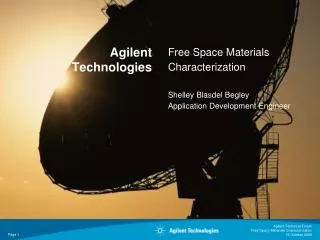
Computer (not required for PNA) Network Analyzer 85071E Materials Measurement Software Sample holder fixtured between two antennae Transmission Free-Space System GP-IB or LAN
l Transmission Reflection (S21 ) (S11 ) Transmission Free-Space • Material assumptions: • Flat parallel faced samples • Sample in non-reactive region • Beam spot is contained in sample • Known thickness > 20/360 λ
Non-Contacting method for High or Low Temperature Tests. Free Space with Furnace
Agilent Technical Forum Free Space Materials Characterization Free Space 75-110GHz Quasi-Optical System
Reflectivity Measurement System Computer (not required for PNA) Network Analyzer with Time Domain option GP-IB or LAN 85071E Materials Measurement Software with Reflectivity Option 200 NRL Arch Fixture with MUT
NRL Arch Results in dB port 1 port 2 S21 Incident Wave Reflected Wave MUT
Resonant Cavity System Computer (not required for PNA) Network Analyzer GP-IB or LAN Resonant Cavity Software Resonant Cavity with sample connected between ports.
empty cavity sample inserted Q c Q s f f f s c Resonant Cavity Technique fc = Resonant Frequency of Empty Cavity fs = Resonant Frequency of Filled Cavity Qc = Q of Empty Cavity Qs = Q of Filled Cavity Vs = Volume of Empty Cavity Vc = Volume of Sample ASTM 2520
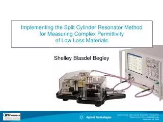
Resonant Cavity Fixtures ASTM 2520 Waveguide Resonators Agilent Split Cylinder Resonator IPC TM-650-2.5.5.5.13 Split Post Dielectric Resonators from QWED