Download
1 / 32
320 likes | 348 Vues
Explore the status of the JLab IR Demo FEL featuring lasing capabilities, energy recovery, and high-power production, advancing FEL technology for efficient and flexible operation.

E N D
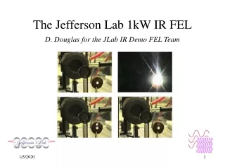
The Jefferson Lab 1kW IR FEL D. Douglas for the JLab IR Demo FEL Team
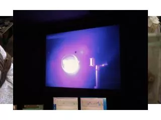
Status of IR Demo • Lasing • 1.72 kW CW @ 3 mm • kW-class tunable light at 3, 5, and 6 mm • 3rd and 5th harmonic lasing • lasing with tapered/inverse tapered wiggler • High flux short pulse x-ray production via Thomson scattering • Accelerator Technology • energy recovery with energy compression while lasing • Emergent user program
FEL Performance Dl/l~1/Nper Coherent Harmonics 7th 6th 5th
FEL Concept In contrast to “traditional” FELs (high extraction efficiency, high micropulse energy, high bunch charge, high peak current, low repetition rate) the JLAB FEL is a (40 period) wiggler-driven optical cavity resonator featuring • low extraction efficiency, low micropulse energy • high average power via high repetition rate • energy recovering SRF linac driver
Virtues of the SRF driver: • CW high repetition rate • high beam quality modest bunch charges (60 pC) give moderate peak current (60 A) and good beam brightness “less is more” • energy recovery • improves system efficiency (ratio of output to wall plug power) • reduces demands on RF (power, windows, & cost) • alleviates radiation control problems (dump beam below neutron production threshold)
Schematic • 10 MeV/5 mA injector • Single, 8-cavity JLab cryomodule accelerating to ~42 MeV • transport to wiggler • wiggler immediately after linac - avoids CSR • transverse matching/bunch compression • energy-recovery transport from wiggler to 10 MeV dump • large momentum acceptance • variable momentum compaction
Beam Dynamics Issues • Numerous issues influence design and operation of recirculating/energy recovering SRF linacs • High brightness source performance/reliability • Space charge • CSR • BBU • HOM power dissipation • FEL/RF interaction • Environmental impedances/wakefields • Management, recirculation, and energy recovery of beam with large momentum spread or otherwise degraded phase space
Beam Dynamics Issues • None of these phenomena limit performance of IR Demo FEL, but may affect future JLab FELs or any of a broader class of related linacs • All are under study analytically, numerically, and empirically (using the IR Demo as a test-bed) • Results are now emerging • R. Li (MOE01, “Analysis and Simulation on the Enhancement of the CSR Effects”) • L. Merminga (THC04, “Specifying HOM-Power Extraction Efficiency in a High Average Current, Short Bunch Length SRF Environment”) • Recirculation, management, and energy recovery of a large (possibly degraded) phase space
Recirculation/Energy Recoveryhas two technical issues: • 1st– FEL interaction inflates momentum spread; in IR Demo FEL we need 5% (or greater) recirculator acceptance • 2nd – Acceptance must be provided in an operationally flexible system – large relative energy spread (2 MeV @ 40 MeV = 5%) becomes HUGE (2 MeV @ 10 MeV = 20%) at the dump, so must energy compress during energy recovery
1. Momentum Acceptance • Need only ~1-2% upstream of laser (drive beam inherent energy spread small), but need ~5% downstream (FEL induced energy spread large) • Use recirculator based on Bates design (reverse bending & dispersion modulation for compaction control) • large acceptance (~8%) • tuneable momentum compactions (M56, T566) • spot sizes at dispersed locations very large while lasing (can be > 10 cm)
1 cm FEL on FEL off Spot sizes, hx=0.4 m
2. Energy Recovery • Emerging as keystone technology for high efficiency/high performance/low cost accelerators (FEL drivers, colliders, light sources…) • alleviates RF system demands, cost, dumped radiation power, but • requires robust transport systems • In FEL drivers, it relies on large acceptance, operationally flexible transport systems to provide appropriate longitudinal performance • IR Demo parameters (1497 MHz, DE/E > 5%) longitudinal match through 2nd order to compensate lattice momentum compactions & RF waveform slope and curvature
Longitudinal Matching Scenario • Requirements on phase space: • high peak current (short bunch) at FEL • bunch length compression at wiggler • “small” energy spread at dump • energy compress while energy recovering • “short” RF wavelength/long bunch get slope and curvature right
E E E E f f f f E E f f
z 2.5 psec E 15 KeV z 2.5 psec E 100 KeV z 0.4 psec E 100 KeV z 0.4 psec E 2 MeV z 30 psec E2 MeV z 30 psec E 100 keV
lasing off lasing on 6-poles off 6-poles on Why We Need the “Right” T566
E (MeV) lasing off lasing on t (nsec) 6-poles off 6-poles on Phase space at 10 MeV Dump
IR Upgrade FEL • ~1 kW delivered using 1/2% extraction efficiency, 200 kW linac (40 MeV, 5 mA) • Upgrade to ~10 kW by • doubling extraction efficiency (1/2% 1%) • increasing linac power by factor of ~10 • doubled current (5 mA 10 mA) • increased energy (35-48 MeV 85-210 MeV) • Three module linac – one with 7-cell JLab module (C. Hovater; TUC12, “RF Control Requirements for the CEBAF Energy Upgrade Cavities) • Increased power accommodated using longer (32 m) R5 optical cavity
Upgrade Status • 9.3 M$ U.S. Navy funding delivered • Design underway • THC03, “Driver Accelerator Design for the 10 kW Upgrade of the Jefferson Lab IR FEL” • Follow-on funding anticipated in FY2001 • Beam operations to start in fall of 2002
Acknowledgments • IR Demo FEL Project Team & friends: S. V. Benson G. Biallas J. Bisognano C. L. Bohn J. Boyce D. Bullard R. Campisi L. Cardman D. Douglas H. F. Dylla R. Evans D. Engwall E. Feldl J. Flanz J. Fugitt A. Grippo J. Gubeli R. Hill C. Hovater K. Jordan J. Karn G. A. Krafft D. Kehne C. Leemann R. Legg R. Li H. Liu L. Merminga G. R. Neil D. Oepts P. Piot J. Preble M. Shinn C. Sinclair T. Siggins J. Song R. Walker D. Vennhaus G. Williams B. C. Yunn • Support by: • US Navy • Commonwealth of Virginia • Industrial partners through the Laser Processing Consortium • US DOE under contract number DE-AC05-84ER40150
E E E E f f f f E E f f Longitudinal Matching Scenario • Requirements on phase space: • high peak current (short bunch) at FEL • bunch length compression at wiggler • “small” energy spread at dump • energy compress while energy recovering • “short” RF wavelength/long bunch get slope and curvature right
E E E E f f f f z 2.5 psec E 15 KeV z 2.5 psec E 100 KeV z 0.4 psec E 100 KeV E z 0.4 psec E 2 MeV E f f z 30 psec E2 MeV z 30 psec E 100 keV
lasing off lasing on 6-poles off 6-poles on Why We Need the “Right” T566
lasing off lasing on 6-poles off 6-poles on Why We Need the “Right” T566
lasing off lasing on 6-poles off 6-poles on Why We Need the “Right” T566