Computer Organization Fundamentals Overview
420 likes | 506 Vues
Learn the basics of computer organization, including memory structures, registers, buses, and fetch/execute cycles. Understand how instructions are processed in a simple CPU model.

Computer Organization Fundamentals Overview
E N D
Presentation Transcript
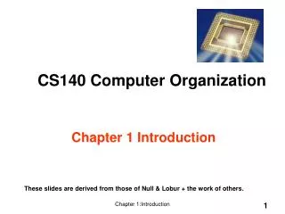
Chapter 3: Computer Organization Fundamentals Prof. Ben Lee Oregon State University School of Electrical Engineering and Computer Science
Chapter Goals Understand the organization of a computer system and its components. Understand how assembly instructions are executed on the processor. Ch. 3: Computer Organization Fundamentals
Computer Organization Ch. 3: Computer Organization Fundamentals
Memory • Random Access Memory • Holds instrutions (program) and data • Unified • Separate instruction and data memory • Organized into consecutive addressable memory words. • 1 memory word • Memory data size • Size of the information accessed by the CPU (CPU register size) • Manufacturer’s definition Ch. 3: Computer Organization Fundamentals
Registers Some important registers: • PC (Program Counter) – holds the address of the next inst. to be fetched from memory • MAR (Memory Address Register) – holds the address of the next instruction or data to be fetched from memory. • MDR (Memory Data Register) – hold the information (word) to be sent to/from memory. • AC (accumulator) – a special register which holds the data to be manipulated by the ALU. • IR (Instruction Register) – holds the instruction to be decoded by the Control Unit (CU). Ch. 3: Computer Organization Fundamentals
ALU AC Internal Data Bus PC MDR MAR IR Internal control signals CU To/from memory and I/O devices … … External control signals A Pseudo-CPU Instruction Format opcode address +1 Ch. 3: Computer Organization Fundamentals
Bus-Register Connections Internal Data Bus Enable Output Tri-State Buffer Enable Input Out 0 X Hi-Z 1 0 0 1 1 1 Register CLK Input Enable Ch. 3: Computer Organization Fundamentals
Bus-Register Connections Internal Data Bus Enable Output Tri-State Buffer Enable Input Out 0 X Hi-Z 1 0 0 1 1 1 Register CLK Input Enable Select MUX 0 1 To ALU/Memory From ALU/Memory Ch. 3: Computer Organization Fundamentals
Fetch and Execute Cycle • A series of steps (i.e., micro-operations) a computer takes to fetch and execute one instruction. • Each micro-operation requires a clock cycle. • Fetch and execute cycle => Instruction Cycle. • Number of micro-operations required to fetch an instruction is usually the same. • Number of micro-operations required to execute each instruction differsdepending on • Complexity of the instruction • e.g., Multiply takes longer than Add • Available hardware • e.g., Multiplier vs. no multiplier hardware Ch. 3: Computer Organization Fundamentals
Fetch Cycle • Need to describe what has to happen in each cycle. • Will use register transfer operations to describe the movement of data. Fetch Cycle Cycle 1: MAR ⟵ PC Cycle 2: MDR ⟵ M[MAR] ; Read the content of memory ; location pointed to by MAR Cycle 3: IR ⟵ MDR(opcode), MAR ⟵ MDR(address) Cycle 4: PC ⟵ PC + 1 Go to beginning of Execute cycle Note: Cycles 2 and 4 can be performed at the same time. Ch. 3: Computer Organization Fundamentals
Instruction Format opcode address Legend Instruction Address Data Register Transfers & Control Signals Fetch Cycle (Step 1) ALU Cycle 1: MAR ⟵ PC AC Internal Data Bus PC_OUTenable IR MARenable PC PC +1 PC MDR MAR Internal control signals CU Memory … … … Instruction opcode address PC External control signals … Ch. 3: Computer Organization Fundamentals
Instruction Format opcode address Legend Instruction Address Data Register Transfers & Control Signals Fetch Cycle (Step 2) ALU Cycle 2: MDR M[MAR], PC PC + 1 AC Internal Data Bus MDRenable IR PCenable PC PC PC+1 Instruction +1 PC MDR MAR Read Internal control signals CU Memory … … … Instruction opcode address PC External control signals … Ch. 3: Computer Organization Fundamentals
Instruction Format opcode address Legend Instruction Address Data Register Transfers & Control Signals Fetch Cycle (Step 3) ALU Cycle 3: IR ⟵ MDR(opcode), MAR ⟵ MDR(address) AC Internal Data Bus MDR_OUTenable IR IRenable PC+1 Instruction PC address MARenable opcode +1 PC MDR MAR Internal control signals CU Memory … … … Instruction opcode address PC External control signals … Ch. 3: Computer Organization Fundamentals
Execute Cycle • Execute cycle depends on the instruction • Will describe execute cycle based on instruction in the pseudo-ISA: • Data transfer Instructions • LDA x (Load Accumulator) ✓ • STA x (Store Accumulator) ✓ • Arithmetic and Logical Instructions • ADD x (Add to accumulator) ✓ • SUB x (Subtract from accumulator) • NAND x (Logical NAND to accumulator) • SHFT (Shift accumulator) • Control Transfer • J x (Jump to x) ✓ • BNE x (Branch conditionally to x) ✓ Ch. 3: Computer Organization Fundamentals
Execute Cycle Memory … Instruction LDA x PC … AC => Operand Operand x … Example: LDA x (Load Accumulator) Execute Cycle Cycle 1: MDR ⟵ M[MAR] Cycle 2: AC ⟵ MDR Return to the beginning of the instruction cycle Ch. 3: Computer Organization Fundamentals
Instruction Format opcode address Legend Instruction Address Data Register Transfers & Control Signals Execute Cycle (Step 1) ALU LDA x Cycle 1: MDR ⟵ M[MAR] AC Internal Data Bus MDRenable IR PC+1 Instruction Operand x LDA +1 PC MDR MAR Read Internal control signals CU Memory … … … Instruction LDA x PC External control signals … Operand x Ch. 3: Computer Organization Fundamentals …
Instruction Format opcode address Legend Instruction Address Data Register Transfers & Control Signals Execute Cycle (Step 2) ALU LDA x Cycle 2: AC ⟵ MDR AC ACenable Operand Internal Data Bus MDR_OUTenable IR PC+1 Operand x LDA +1 MDR PC MAR Internal control signals CU Memory … … … Instruction LDA x PC External control signals … Operand x Ch. 3: Computer Organization Fundamentals
Execute Cycle Memory … Instruction STA x PC … AC <= Operand Operand x … Example: STA x (Store Accumulator) Execute Cycle Cycle 1: MDR ⟵ AC Cycle 2: M[MAR] ⟵ MDR Return to the beginning of the instruction cycle Ch. 3: Computer Organization Fundamentals
Instruction Format opcode address Legend Instruction Address Data Register Transfers & Control Signals Execute Cycle (Step 1) ALU STA x Cycle 1: MDR ⟵ AC AC Operand Internal Data Bus AC_OUTenable MDRenable IR Operand Instruction PC+1 x STA +1 PC MDR MAR Internal control signals CU Memory … … … Instruction STA x PC External control signals … x Ch. 3: Computer Organization Fundamentals …
Instruction Format opcode address Legend Instruction Address Data Register Transfers & Control Signals Execute Cycle (Step 2) ALU STA x Cycle 2: M[MAR] ⟵ MDR AC Operand Internal Data Bus MDRenable IR PC+1 Operand x STA +1 PC MDR MAR Write Internal control signals CU Memory … … … Instruction STA x PC External control signals … Operand x Ch. 3: Computer Organization Fundamentals
Execute Cycle Effective Address - address that points to the operand Memory … Instruction ADD x PC … AC + Operand2 Result Operand1 x … Example: ADD x (Add to Accumulator) Execute Cycle Cycle 1: MDR ⟵ M[MAR] ; Read operand Cycle 2: AC ⟵ AC + MDR ; Add and transfer result to AC Return to the beginning of the instruction cycle Ch. 3: Computer Organization Fundamentals
Instruction Format opcode address Legend Instruction Address Data Register Transfers & Control Signals Execute Cycle (Step 1) ALU ADD x Cycle 1: MDR ⟵ M[MAR] AC Operand1 Internal Data Bus MDRenable IR Operand2 Instruction PC+1 x ADD +1 PC MDR MAR Read Internal control signals CU Memory … … … Instruction ADD x PC External control signals … Operand2 x Ch. 3: Computer Organization Fundamentals …
Instruction Format opcode address Legend Instruction Address Data Register Transfers & Control Signals Execute Cycle (Step 2) ALU ADD ADD x Cycle 2: AC ⟵ AC + MDR AC ACenable Operand2 Result Internal Data Bus MDR_OUTenable IR Operand2 PC+1 x ADD +1 PC MDR MAR Internal control signals CU Memory … … … Instruction ADD x PC External control signals … Operand2 x Ch. 3: Computer Organization Fundamentals
Execute Cycle Memory … Branch Target Address J x PC … Next Instruction x Example: J x (Jump to x) Execute Cycle Cycle 1: PC ⟵ MDR(address) Return to the beginning of the instruction cycle Ch. 3: Computer Organization Fundamentals
Instruction Format opcode address Legend Instruction Address Data Register Transfers & Control Signals Execute Cycle (Step 1) ALU B x Cycle 1: PC ⟵ MDR(address) AC Internal Data Bus MDR_OUTenable IR PCenable PC+1 Instruction x x B +1 PC MDR MAR Internal control signals CU Memory … … … Instruction B x PC External control signals … Next Instruction x Ch. 3: Computer Organization Fundamentals
Execute Cycle Memory … Branch Target Address BNE x PC … Next Instruction x Example: BNE x (Branch Conditionally to x) Execute Cycle Cycle 1: If (Z != 1) then PC ⟵ MDR(address) Return to the beginning of the instruction cycle Ch. 3: Computer Organization Fundamentals
Z=1 if last ALU operation is zero Instruction Format opcode address Z MDR_OUTenable Branch PCenable Legend Instruction Address Data Register Transfers & Control Signals Execute Cycle (Step 1) ALU BZ x AC Cycle 1: If (Z != 1) then PC ⟵ MDR(address) Internal Data Bus MDR_OUTenable IR PCenable PC+1 Instruction x x BZ +1 PC MDR MAR Internal control signals CU Memory … … … Instruction BNE x PC External control signals … Next Instruction x Ch. 3: Computer Organization Fundamentals
One More Example… Memory Useful for indexing arrays! … Effective Address - address that points to the operand Instruction LDA x PC … x EA AC … => Operand Operand EA Example: LDA (x) (Load Accumulator Indirect) Execute Cycle Cycle 1: MDR ⟵ M[MAR] ; Read effective address (EA) Cycle 2: MAR ⟵ MDR ; Move EA to MAR Cycle 3: MDR ⟵ M[MAR] ; Read operand Cycle 4: AC ⟵ MDR ; Move operand to AC Return to the beginning of the instruction cycle Ch. 3: Computer Organization Fundamentals
Instruction Format opcode address Legend Instruction Address Data Register Transfers & Control Signals Execute Cycle (Step 1) ALU LDA (x) Cycle 1: MDR ⟵ M[MAR] AC Internal Data Bus MDRenable IR EA Instruction PC+1 x LDAI +1 PC MDR MAR Read Internal control signals CU Memory … … … LDAI x PC … External control signals x EA … Operand EA Ch. 3: Computer Organization Fundamentals
Instruction Format opcode address Legend Instruction Address Data Register Transfers & Control Signals Execute Cycle (Step 2) ALU LDA (x) Cycle 2: MAR ⟵ MDR AC Internal Data Bus MDR_OUTenable IR EA EA PC+1 PC x MARenable LDAI +1 PC MDR MAR Internal control signals CU Memory … … … LDAI x PC … External control signals x EA … Operand EA Ch. 3: Computer Organization Fundamentals
Instruction Format opcode address Legend Instruction Address Data Register Transfers & Control Signals Execute Cycle (Step 3) ALU LDA (x) Cycle 3: MDR ⟵ M[MAR] AC Internal Data Bus MDRenable IR EA PC+1 PC Operand x LDAI EA +1 PC MDR MAR Read Internal control signals CU Memory … … … LDAI x PC … External control signals x EA … Operand EA Ch. 3: Computer Organization Fundamentals
Instruction Format opcode address Legend Instruction Address Data Register Transfers & Control Signals Execute Cycle (Step 4) ALU LDA (x) Cycle 4: AC ⟵ MDR AC ACenable Operand Internal Data Bus MDR_OUTenable IR Operand PC+1 EA LDAI +1 PC MDR MAR Internal control signals CU Memory … … … LDAI x PC … External control signals x EA … Operand EA Ch. 3: Computer Organization Fundamentals
Last Example…(I promise!) EA+1 x EA EA+1 EA x EA EA Operand EA Operand Operand Memory … Instruction LDAI- x PC … x -1 EA EA+1 => EA EA+1 AC … => Operand Operand EA Example: LDA -(x) (Load Accumulator Indirect with Pre-decrement) Useful for stepping through arrays Execute Cycle Cycle 1: MDR ⟵ M[MAR] ; Read EA+1 Cycle 2: MDR ⟵ MDR - 1; Decrement EA Cycle 3: M[MAR] ⟵ MDR; Store it back in location x (i.e., M[x]) Cycle 4: MAR ⟵ MDR ; Move EA to MAR Cycle 5: MDR ⟵ M[MAR] ; Read operand Cycle 6: AC ⟵ MDR ; Move operand to AC Ch. 3: Computer Organization Fundamentals
ALU ADD -(x) AC Internal Data Bus PC MDR MAR IR -1 Internal control signals CU To/from memory and I/O devices … … • Assume MDR can decrement itself External control signals Easiest Way Instruction Format opcode address +1 Ch. 3: Computer Organization Fundamentals
Hard Way (1) Instruction Format ALU opcode address ADD -(x) • MDR does not have the capability to decrement itself • Must use AC and ALU! AC Internal Data Bus PC MDR MAR IR +1 Internal control signals CU To/from memory and I/O devices … … External control signals Ch. 3: Computer Organization Fundamentals
Hard Way (2) EA+1 x EA+1 EA+1 EA+1 EA EA EA x EA EA EA Operand EA Operand Operand Execute Cycle Cycle 1: MDR ⟵ M[MAR] ; Read EA+1 Cycle 2: AC ⟵ MDR ; Move EA+1 to AC Cycle 3: AC ⟵ AC - 1 ; Decrement EA+1 Cycle 4: MDR ⟵ AC ; Move EA to MDR Cycle 5: M[MAR] ⟵ MDR ; Store it back in location x (i.e., M[x]) Cycle 6: MAR ⟵ MDR ; Move EA MAR Cycle 7: MDR ⟵ M[MAR] ; Read operand Cycle 8: AC ⟵ MDR ; Move operand to AC Note: Cycles 5 and 6 can be performed at the same time. Ch. 3: Computer Organization Fundamentals
Pseudo-CPU with TEMP Register ALU TEMP AC Internal Data Bus PC MDR MAR IR +1 Internal control signals CU To/from memory and I/O devices … … External control signals • There may be times when the content of AC has to be preserved. • TEMP increases the flexibility for implementing more complicated instructions, e.g., STA -(x), LDA (x)+, STA(x)+. Ch. 3: Computer Organization Fundamentals
What We Will See Later… • AVR Microcontroller • Used in low-end embedded systems Ch. 3: Computer Organization Fundamentals
What You Will See in ECE 472… • 5-stage pipeline • Used in high-end embedded systems, e.g., Mobile devices. Ch. 3: Computer Organization Fundamentals
What You Will See in ECE 570… • SuperScalar • OoO (out-of-order execution) • Speculation • Used in PCs and servers. Branch Prediction Instruction Cache Fetch Instruction Queue Register File Dispatch Reservation Stations Load/Store Branch Integer Integer FP Forwarding Bypass Reorder Buffer Data Cache Commit Ch. 3: Computer Organization Fundamentals
Questions? Ch. 3: Computer Organization Fundamentals