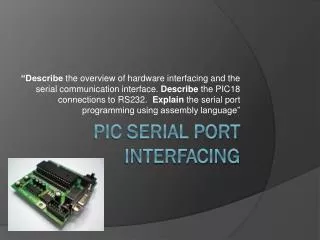
PIC18 Serial Port Programming in Assembly
250 likes | 554 Vues
Learn about serial communication, data transfer rates, and how to program the PIC18's serial port in assembly language.

PIC18 Serial Port Programming in Assembly
E N D
Presentation Transcript
Objective • Explain serial communication protocol • Describe data transfer rate and bps rate • Interface the PIC18 with an RS232 connector • Describe the main registers used by serial communication of the PIC18 • Program the PIC18 serial port in Assembly
Introduction • Computers transfer data in two ways: Parallel and Serial. • Parallel: Eight or more data lines, few feet only, short time • Serial: Single data line, long distance • The PIC18 has serial communication capability built into it.
PIC18 Connection to RS232 Line driver (a) Inside MAX232 (b) its Connection to the PIC18
PIC18 Serial Port Programming in Assembly • USART has both • Synchronous • Asynchronous • 6 registers • SPBRG • TXREG • RCREG • TXSTA • RCSTA • PIR1 Rx Port Tx Port
SPBRG Register and Baud Rate in the PIC18 • The baud rate in is programmable • loaded into the SPBRG decides the baud rate • Depend on crystal frequency • BR = FFosc4*16*(X+1)( Baud rate Formula If Fosc = 10MHz X = (156250/Desired Baud Rate) - 1
TXREG Register • 8-bit register used for serial communication in the PIC18 • For a byte of data to be transferred via the Tx pin, it must be placed in the TXREG register first. • The moment a byte is written into TXREG, it is fetched into a non-accessible register TSR MOVFFPORTB, TXREG • The frame contains 10 bits RCREG Register • 8-bit register used for serial communication in the PIC18 • When the bits are received serially via the Rx pin, the PIC18 deframes them by eliminating the START and STOP bit, making a byte out of data received and then placing it in the RCREG register MOVFFRCREG, PORTB
Programming the PIC18 to Transfer Data Serially • TXSTA register = 20H: Indicating asynchronous mode with 8-bit data frame, low baud rate and transmit enabled • Set Tx pin an output (RC6) • Loaded SPBRG for baud rate • Enabled the serial port (SPEN = 1 in RCSTA) • The character byte to transmit must be written into TXREG • Keep Monitor TXIF bit • To transmit next character, go to step 5
Example ;Write a program for the PIC18 to transfer the letter 'G' serially ;at 9600 baud continuously. Assume XTAL = 10 MHz MOVLW B'00100000' MOVWF TXSTA MOVLW D'15'; 9600 bps MOVWF SPBRG BCF TRISC, TX BSF RCSTA, SPEN OVER MOVLW A'G' S1 BTFSS PIR1, TXIF BRA S1 MOVWF TXREG BRA OVER
Programming the PIC18 to Receive Data Serially • RCSTA register = 90H: To enable the continuous receive in addition to the 8-bit data size option • The TXSTA register = 00H: To choose the low baud rate option • Loaded SPBRG for baud rate • Set Rx pin an input • Keep Monitor RCIF bit • Move RCREG into a safe place • To receive next character, go to step 5
Example ;Write a program for the PIC18 to receive data serially and ;put them on PORTB. Set the baud rate at 9600, 8-bit data ;and 1 stop bit MOVLW B'10010000' MOVWF RCSTA MOVLW D'15' MOVWF SPBRG BSF TRISC, RX CLRF TRISB R1 BTFSS PIR1, RCIF BRA R1 MOVFF RCREG, PORTB BRA R1
Increasing the Baud Rate • Faster Crystal • May not be able to change crystal • TXSTA.BRGH bit • Normally used low • Can be set high • Quadruples rate when set high
Baud Rate Error Calculation • ??? Errors in the baud rate? Yep! • Caused by using integer division in rate generator