Download
1 / 16
160 likes | 160 Vues
service repair manual

E N D
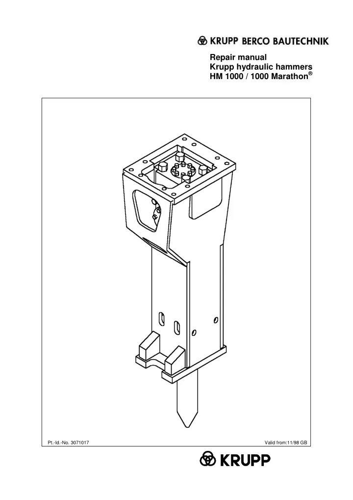
Repair manual Krupp hydraulic hammers HM 1000 / 1000 Marathon® Pt.-Id.-No. 3071017 Valid from:11/98 GB
Repair manual HM 1000 / 1000 Marathon® Contents Chapter Title Version Page 1. 1.1 General........................................................................................11/98............... Explanation of the symbols in the repair manual .................................................. 1 2 2. 2.1 2.2 2.3 2.4 Operational safety.......................................................................11/98............... General................................................................................................................ Accident prevention regulations............................................................................ Tools, measuring and testing equipment............................................................... Operating media/consumables.............................................................................. 1 1 1 2 2 3. 3.1 3.2 3.3 3.3.1 3.3.2 3.3.3 3.3.4 3.3.5 Tools............................................................................................11/98............... General tools........................................................................................................ Toolbox 3............................................................................................................. Special accessories.............................................................................................. Accumulator filling device..................................................................................... Power wrench....................................................................................................... Heli-Coil tools....................................................................................................... Fitting aid for percussion piston............................................................................ Press-out aid for wear bushes............................................................................... 1 1 2 3 3 4 4 5 5 4. 4.1 4.2 4.3 4.4 4.5 4.6 4.7 4.8 4.9 4.10 4.11 4.12 4.13 Dismantling the hydraulic hammer............................................11/98............... Removing the working tool................................................................................... Removing the percussion mechanism of the HM 1000 from the hammer box....... Removing the high-pressure accumulator............................................................. Removing the control slide valve.......................................................................... Removing the AutoControl - valve........................................................................ Removing the perforated disk............................................................................... Removing the cylinder cover................................................................................ Removing the percussion piston and sealing bush................................................ Removing the cylinder.......................................................................................... Removing the external-thread flange.................................................................... Removing the DustProtector................................................................................. Removing the locking pins for the retainer bars in the lower hammer part............ Removing the plastic bushes................................................................................ 1 1 2 3 4 5 6 6 8 8 9 10 11 11 5. 5.1 5.2 5.3 5.4 5.5 5.5.1 5.5.2 5.5.3 Checking the hammer box.........................................................11/98............... Checking for cracks and indentations.................................................................... Wear to the bottom plate...................................................................................... Checking the elastic pad....................................................................................... Checking the damping elements........................................................................... Checking the guide plates and the dust collar....................................................... Checking the guide plates..................................................................................... Checking the upper guide..................................................................................... Checking the dust collar....................................................................................... 1 1 1 2 2 3 3 4 4 Version 11/98 Contents 1
Repair manual HM 1000 / 1000 Marathon® Contents Chapter Title Version Page 6. 6.1 6.2 6.3 6.4 6.5 6.6 6.7 6.8 6.9 6.10 6.11 6.12 6.13 6.14 Assembling the hydraulic hammer........................................................11/98... Tightening torques for screws and screw couplings on the HM 1000..................... Fitting the cylinder................................................................................................ Fitting the percussion piston and sealing bush...................................................... Fitting the cylinder cover...................................................................................... Fitting the AutoControl – valve............................................................................. Fitting the perforated disk..................................................................................... Fitting the control slide valve................................................................................ Fitting the high-pressure accumulator................................................................... Fitting the external-thread flanges........................................................................ Filling the piston accumulator............................................................................... Fitting the HM 1000 percussion mechanism in the hammer box........................... Connecting ContiLube® II to the HM 1000 Marathon®........................................... Fitting the working tool.......................................................................................... Fitting the DustProtector....................................................................................... 1 1 2 2 3 5 6 6 6 7 8 10 11 12 13 7. 7.1 7.2 7.3 7.4 7.5 7.6 Changing the seals.................................................................................11/98... Changing the cylinder seals.................................................................................. Changing the seals between cylinder and cylinder cover...................................... Changing the seals on the external-thread flange................................................. Changing the seals on the control casing cover.................................................... Changing the seals on the high pressure accumulator.......................................... Changing the seals on the sealing bush................................................................ 1 1 3 3 3 4 4 8. 8.1 8.2 8.3 8.4 8.5 8.6 8.7 8.8 8.9 8.10 8.11 8.12 8.13 8.14 8.15 8.16 8.17 8.18 8.19 Repair work.............................................................................................11/98... Changing the Allen screws on the high-pressure accumulator............................... Changing the high-pressure accumulator.............................................................. Changing the tie rods............................................................................................ Removing scores from control slide valve and bore.............................................. Removing scores on percussion piston and cylinder bore..................................... Replacing retainer bars and working tool.............................................................. Changing the wear bushes.................................................................................... Replacing the complete hammer box.................................................................... Replacing guide plates and damping elements in hammer box............................. Replacing the dust collar in the hammer box........................................................ Replacing the wear protection set......................................................................... Replacing the DustProtector................................................................................. Repairing cracked welds....................................................................................... Replacing the bottom plate on the hammer box.................................................... Reworking the retainer pins for the damping elements.......................................... Weld seam preparation........................................................................................ Preheating temperature........................................................................................ Fillers................................................................................................................... Post-treatment of welds........................................................................................ 1 1 1 2 3 3 4 4 8 8 8 9 9 10 10 11 11 11 11 11 Authorised dealers and regional service centres Version 11/98 Contents 2
Repair manual HM 1000 / 1000 Marathon® 1. General In order to maintain the operational safety of all versions of the HM 1000 hydraulic hammer, repair work should only be carried out by Krupp trained specialists using genuine Krupp spare parts. Krupp trained specialists know which parts need replacing and when. Although this repair manual applies to all versions of the HM 1000 hydraulic hammer, the manual refers only to the HM 1000 by way of simplification. Specific differences between the versions are however highlighted. Version 11/98 Chapter 1 1
Repair manual HM 1000 / 1000 Marathon® 1.1 Explanation of the symbols in the repair manual To emphasise their importance, certain points in the repair manual are marked with symbols, which are described below. Theses passages contain information on the correct use of the hydraulic tool and are aimed at avoiding mistakes during operation. Please note! Passages marked in this way contain safety information and instructions aimed at avoiding damage. Warning! Passages marked in this way contain safety information and instructions aimed at preventing accidents and avoiding injury. Caution! Version 11/98 Chapter 1 2
Repair manual HM 1000 / 1000 Marathon® 2. Operational safety Caution! 2.1 General In order to maintain the operational safety of the hydraulic hammer, repair work should only be carried out by trained specialists using genuine Krupp spare parts. This work should therefore only be entrusted to Krupp trained specialists who know which spare parts need replacing and when. The hammer's integrated piston accumulator is pressurised. Before dismantling the hydraulic hammer and before removing the complete filling valve “G”, the piston accumulator depressurised. Never use nails, screwdrivers or similar objects to bleed off the gas since this would damage the filling valve. Bleed off the gas using only the nozzle of the filling/test hose. Never use your fingers to check the alignment of the working tool recesses to the oblong holes for the locking bars. Never dismantle a hydraulic hammer which is still hot from running as there is a high risk of injury through burns. Always wait until the hammer has cooled down before dismantling it. Collect any oil which runs out and dispose of it correctly. must be fully 2.2 Accident prevention regulations Caution! To avoid the possibility of injury, please observe the following instructions Before starting work: Please familiarise yourself with the repair manual and the appropriate regulations before starting work on the hydraulic hammer. When using or working on hydraulic hammers in the countries of the European Union, the regulations of the EC machinery directive 98/37/EG must be observed and followed, as must national accident prevention regulations and regulations covering pressurised vessels. In countries outside the European Union, the valid local statutes and regulations will apply. The hydraulic hammer should only be repaired by specialists. When lifting/transporting the hydraulic hammer, use only the lug provided and hoisting equipment with sufficient capacity. Clear hand signals must be agreed on with the hoist operator beforehand. Never stand beneath hoisted loads. Stand the hydraulic hammer in a suitable device and secure it against falling over. The repair area must be clear and easily accessible. Always wear protective glasses when fitting or removing the working tool since metal splinters may fly off when hammering out the locking pins. Working tools should only be fitted as described in the operating manual. Caution Risk of explosion! The piston accumulator must only be filled with nitrogen from the green cylinder. Make sure that no other gas (e.g. air or oxygen) is allowed into the piston accumulator. When attaching the adapter use only Allen screws with a material quality of σs = 640 N/mm2 (material quality 8.8)! Version 11/98 Chapter 2 1
Repair manual HM 1000 / 1000 Marathon® 2.3 Tools, measuring and testing equipment The reassembling the HM 1000 are to be provided by the user (see Chapter 3.1). tools required for dismantling and The special accessories used in this section are listed in Chapter 3.3 2.4 Operating media / consumables Use Comments HP oil HLP 32 Running the HM 1000 In warmer climates, oils with a higher viscosity class should be used. Krupp chisel paste (see operating manual) High- performance bearing grease with solids content Nitrogen N2 Working tool lubrication Filling the - high-pressure accumulator – piston accumulator Removing scores Caution! Abrasive polishing paper, grain 600 Version 11/98 Chapter 2 2
Repair manual HM 1000 / 1000 Marathon® 3. 3.1 Tools General tools The tools required for repair work are listed below: Designation Part ID no. Qty. Sledgehammer 2 kg 1031811 1 Sledgehammer 4 kg 1146433 1 Grease gun cpl. 3034567 1 Slugging ring spanner size 55 0439439 1 Heavy-duty box spanner size 55 0478217 1 Jaw spanner size 41/46 0430613 1 Socket spanner size 24/27 0431002 1 Socket spanner size 22 1031835 1 Socket spanner size 14 3031396 1 Claw spanner size 46/50 0478861 1 Allen key size 22 0209445 1 Allen key size 19 0209253 1 Allen key size 17 0209252 1 Allen key size 14 0204963 1 Allen key size 12 0209251 1 Allen key size 5 0209249 1 Power screwdriver insert size 55 / 1 ½” 1 Adapter 1” J / 1 ½” A 1 Adapter ¾” J / 1” A 1 Screwdriver 8 mm 328143 1 Torque wrench 140-760 Nm / ¾” 1 Version 11/98 Chapter 3 1
Repair manual HM 1000 / 1000 Marathon® 3.2 Toolbox 3 The tools required for service work on the hammers are contained in Toolbox 3 Fig. 1 Toolbox 3 Dimensions Length 760 mm Width 215 mm Height 250 mm Toolbox 3 and contents can be ordered under part ident. no. 3034016. Item Qty. Designation Pt. ID no. - 1 Toolbox, empty 2267014 1 1 Chisel paste 3066065 2 1 Nitrogen cylinder 2l 3034504 3 1 Filler valve 1329516 4 1 Test pressure gauge 1329518 5 1 Hose 1329517 6 1 Test gauge HM 1000 3002794 Pin punch d=15.5 L=130 Claw spanner size 50 with tommy bar 7 1 1848819 8 1 0478861 9 1 Screwdriver size 5 3066376 Fig. 2 Service tools Hexagonal head bolt M 12x150 10 1 0103866 Version 11/98 Chapter 3 2
Repair manual HM 1000 / 1000 Marathon® 3.3 Special accessories This chapter lists the special tools and apparatus which can be purchased from Krupp Berco Bautechnik to equip the workshop. 3.3.1 Accumulator filling device The tools listed in the table below are used to fill the high-pressure accumulator. The filling process also requires the nitrogen cylinder (2/2) and the filler valve (2/3) from Toolbox 3. Item Designation Pt. ID no. Filling device cpl. with pressure gauge, check valve, Phillips screwdriver and tommy screw, as well as items 1 to 3 Filling hose 0920415 1 1329805 2 Phillips screw insert 1329890 3 Mushroom head adapter 1329889 Fig. 3 Accumulator filling device Version 11/98 Chapter 3 3
Repair manual HM 1000 / 1000 Marathon® 3.3.2 Power wrench You can choose between an electronic or a hydraulic power wrench. 3.3.3 Heli-Coil tools The tools listed in the table below are used to replace the Heli-Coil inserts. Fig. 4 Electronic power wrench Item. Designation Pt. ID no. Use Screw tap M 14 Threaded insert M 14 Screw-in tool M 14 Screw tap M 16 Threaded insert M 16 Screw-in tool M 16 Screw tap M 20 Threaded insert M 20 Screw-in tool M 20 Screw tap M 30 Threaded insert M 30 Screw-in tool M 30 Screw tap RD 36x5 Threaded insert RD 36x5 Screw-in tool RD 36x5 1 3066426 Cylinder- cover (P + T) 2 1031946 3 3066427 4 0920358 High- pressure accumulator 5 1031989 6 0920354 7 0920359 Fig. 5 Hydraulic power wrench Cylinder cover (Control system) 8 1031529 9 0920355 10 0920360 11 0478261 Adapter 12 0920356 13 - Fig. 6 Heli-Coil tools Lower hammer part 14 3031774 15 3066418 Version 11/98 Chapter 3 4
Repair manual HM 1000 / 1000 Marathon® 3.3.4 Fitting aid for percussion piston Designation Pt. Id No. Eye bolt 0206700 Fig. 7 Fitting aid 3.3.5 Press-out aid for wear bushes Item Designation Pt. Id No. - Press-out tool, compl. - 1 Grip - 2 Screw - 3 Press-out element - Fig. 8 Press-out aid Version 11/98 Chapter 3 5
Repair manual HM 1000 / 1000 Marathon® 4. Dismantling the hydraulic hammer 4.1 Removing the working tool • • Lay the hydraulic hammer on a suitable base. Remove the plugs (1/5) and (1/9) from the hammer box. Using the pin punch from Toolbox 3 (1/7), and a hand-held hammer (1/8), knock the locking pins (1/2) for the retainer bars (1/3) out of the side of the lower hammer part (1/1). • • Caution! Wear protective glasses! Risk of injury from flying metal splinters. • Remove the two sealing plugs (1/4) from the oblong holes for the retainer bars. Remove the retainer bars (1/3). The retainer bars have an M12 thread on the front end. Take an M 12x150 hexagonal head screw from Toolbox 3, screw it into the threaded bore and use it to pull out the retainer bar. Remove the working tool (1/6) from the bore in the lower hammer part and deposit safely. Fig. 1 Removing the working tool • • Version 11/98 Chapter 4 1
Thank you very much for your reading. Please Click Here. Then Get COMPLETE MANUAL. NO WAITING NOTE: If there is no response to click on the link above, please download the PDF document first and then click on it.
Repair manual HM 1000 / 1000 Marathon® 4.2 Removing the percussion mechanism of the HM 1000 from the hammer box Caution! Fig. 2 Unscrewing the adapter from the hammer box • Stand hammer box with hydraulic hammer vertically and secure against falling over. Remove Allen screws (2/2) using Allen key size 22 (2/3) and remove adapter from hammer box using a hoist/crane. Remove elastic pad (Fig. 3). • • Warning! Marathon® version: Remove grease/oil line between ContiLube® II and hydraulic hammer. • Fig. 3 Removing the elastic pad • Screw two eye bolts M24 into the two threaded bores on the upper face of the cylinder cover as far as they will go. Using a hoist/crane, lift the percussion mechanism of the HM 1000 out of the hammer box (Fig. 4). • Caution! • If the percussion mechanism has jammed in the hammer box, e.g. due to heavy contamination, the hoist must not be used as a pulling device with the hammer box held firmly. Secure hammer box against falling over. Stand percussion mechanism of HM 1000 vertically and secure against falling over (e.g. place on a stand similar to that in Fig. 5). Fig. 4 Lifting the percussion mechanism out of the hammer box • • Fig. 5 Stand Version 11/98 Chapter 4 2
Repair manual HM 1000 / 1000 Marathon® 4.3 Removing the high-pressure accumulator • Stand hydraulic hammer vertically and secure against falling over (e.g. on a stand similar to Fig. 5), or lay flat. Caution! If the HM 1000 is still attached to the carrier, the hydraulic system must be depressurised prior to removing the high-pressure accumulator. Fig. 6 Releasing and unscrewing the Allen screws e.g. • On hoses with screw couplings, relieve pressure on check valves and depressurise (open the hose ports on the hammer). Release Allen screws (6/1) on accumulator using a size 14 Allen key (6/2) and screw them out (Fig. 6), removing the locking washers at the same time. Collect any oil which runs out and dispose of it correctly. • • • Remove high-pressure accumulator (Fig. 7). Check threaded insert (part no. 54), replace if necessary. Fig. 7 Removing the high-pressure accumulator Warning! The high-pressure accumulator on the HM 1000 has a capacity of 0.9 l and a max. permissible operating pressure of 200 bar (2900psi). If repairs are necessary, the statutory regulations of the country in question must be observed and followed (see repair manual for high-pressure accumulator, part ident. no. 1855714). Fig. 8 Removing the O-ring and back-up ring Version 11/98 Chapter 4 3