Download
1 / 29
350 likes | 740 Vues
EML 4304L Thermal Fluids Lab Thermal Conduction Experiment # 3. Mechanical Engineering Department FAMU/FSU College of Engineering. Outline. Purpose of the lab Testing Equipment The types of equipment setup Units 3 and 4 Units 1 and 2 Additional components Heat sinks Drain tubes

E N D
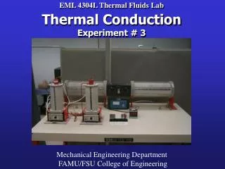
EML 4304L Thermal Fluids LabThermal ConductionExperiment # 3 Mechanical Engineering Department FAMU/FSU College of Engineering
Outline • Purpose of the lab • Testing Equipment • The types of equipment setup • Units 3 and 4 • Units 1 and 2 • Additional components • Heat sinks • Drain tubes • Calculations Needed for Experiment Mechanical Engineering Department FAMU/FSU College of Engineering
PURPOSE • Conduct a series of thermal conduction experiments which examines the effects on heat transfer with varying cross-sectional area and distance. • Using this thermal conduction information derive Fourier’s law of thermal conduction. • Analyze the temperature variance in a series of metal rods that are in physical contact. • From this information determine thermal resistance and contact resistance. Mechanical Engineering Department FAMU/FSU College of Engineering
Testing EquipmentFor Experiments Mechanical Engineering Department FAMU/FSU College of Engineering
Units 1-4 Drain tube Temperature Recorder Adjusting knobs Mechanical Engineering Department FAMU/FSU College of Engineering
On/Off Switches for Units 1-4 Thermocouple Selector 1-10 Unit Selector 1-4 Mechanical Engineering Department FAMU/FSU College of Engineering
Temperature adjustor for Units 3-4 Mechanical Engineering Department FAMU/FSU College of Engineering
Digital Temperature Indicator (ºF) Mechanical Engineering Department FAMU/FSU College of Engineering
Equipment for Thermal Conduction Test Units #3 and #4 Mechanical Engineering Department FAMU/FSU College of Engineering
Heat flow for units 3 and 4 Mechanical Engineering Department FAMU/FSU College of Engineering
Heat flow for units 3 and 4 Notes: Do NOT adjust the flow valves. Mechanical Engineering Department FAMU/FSU College of Engineering
UNIT #3 Q=KA*ΔT/Δx K = coeff. of therm. conductivity NOTE: K is unknown and must be determined T1 T2 x2 x1 Mechanical Engineering Department FAMU/FSU College of Engineering
UNIT #4 Q=KA*ΔT/Δx K = coeff. of therm. conductivity NOTE: K is unknown and must be determined T1 T10 x2 x1 Mechanical Engineering Department FAMU/FSU College of Engineering
Equipment Thermal Resistance and Contact Resistance Test Units #1 and #2 Mechanical Engineering Department FAMU/FSU College of Engineering
Heat flow for units 1 and 2 Mechanical Engineering Department FAMU/FSU College of Engineering
Heat flow for units 1 and 2 elements are enclosed in the insulating jacket. Figure1 illustrates the schematics of the apparatus. The dimensions of the tapered rod are indicated in Fig. 2. elements are enclosed in the insulating jacket. Figure1 illustrates the schematics of the apparatus. The dimensions of the tapered rod are indicated in Fig. 2. elements are enclosed in the insulating jacket. Figure1 illustrates the schematics of the apparatus. The dimensions of the tapered rod are indicated in Fig. 2. Mechanical Engineering Department FAMU/FSU College of Engineering
Units #1 and #2 Steel (Mg) Cu (Al) Stainless Steel T10 T1 x2 x1 Contact Resistance Mechanical Engineering Department FAMU/FSU College of Engineering
Heat Sinks • One water cooled heat sink is located on each unit • Units #1 and #2 they are located at extreme end of the assembly away from the heat source • Units #3 and #4 are located on the top of each unit • The heat sinks will be used to determine heat lost by each unit. • Q=mwCp(ΔT) Mechanical Engineering Department FAMU/FSU College of Engineering
Drain Tube Flow Rate Calculations Mechanical Engineering Department FAMU/FSU College of Engineering
Drain tubes leading from heat sinks Mechanical Engineering Department FAMU/FSU College of Engineering
Drain tube Graduated cylinder to measure flow rate Also will need a stopwatch to time fluid flow Mechanical Engineering Department FAMU/FSU College of Engineering
Calculations Mechanical Engineering Department FAMU/FSU College of Engineering
Calculations Conservation of Energy (in a perfect world) qin = q out Conservation of Energy (in our world) qin = Cq out Where C is a constant which represents any losses not accounted for. Mechanical Engineering Department FAMU/FSU College of Engineering
Units #1 and #2 Steel (Mg) Cu (Al) Stainless Steel Heat Sink Heat In Qout=Qin Q=mwCp(ΔT) Rt,c= ΔT/Q Mechanical Engineering Department FAMU/FSU College of Engineering
Calculations Thermal Contact Resistance Rt,c = Thermal contact resistance T = Temperature change q = Heat flux Mechanical Engineering Department FAMU/FSU College of Engineering
UNIT #3 Qout Qin Qout=Qin x2 x1 Q=mwCp(ΔT) Q=KAΔT/Δx Mechanical Engineering Department FAMU/FSU College of Engineering
Calculations (1) (2) (1) – Rate of heat flow at the sink mw = mass of cooling water displaced in time t Cp = Specific heat of water at constant pressure T = (Tout - Tin) of cooling water t = time required to displace a volume Vw of water (2) – Relationship between heat flow and temperature difference K = proportionality constant A = cross-sectional area T = temperature difference of the material x = distance Mechanical Engineering Department FAMU/FSU College of Engineering
Calculations • Q=KA ΔT/Δx Q=-KA dT/dx • dT/dx = temperature gradient T dT/dx x Mechanical Engineering Department FAMU/FSU College of Engineering
Errors • Time Flow rate Steady State • Heat Losses Not perfectly insulated Mechanical Engineering Department FAMU/FSU College of Engineering