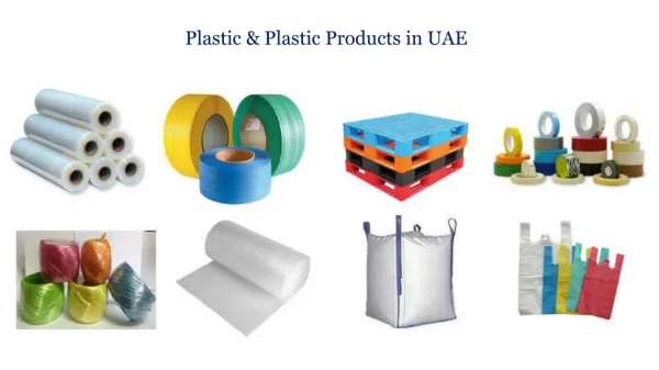
Download
1 / 18
180 likes | 352 Vues
Assessment of Ductile Tearing and Plastic collapse in 304 SS. Andrew Wasylyk. What?. Why?. How?. Conclusions!. Aim.

E N D
Assessment of Ductile Tearing and Plastic collapse in 304 SS Andrew Wasylyk
What? Why? How? Conclusions! Aim • Assessment of defect behavior against crack initiation toughness can be highly pessimistic representations of failure load by unstable tearing or plastic collapse for low yield high toughness materials • We aim to quantify the dynamically evolving relationship between “failure” by crack initiation, crack instability and plastic collapse. • Use a combination of experimental and modeling approaches to quantify the relationship between crack initiation, ductile crack growth and the development of local and global plasticity in standard and novel specimens
What? Why? How? Conclusions! plastic zone Plastic zone Fracture process area Fracture Modes: Competition *Anderson, Fracture Mechanics: Fundamentals and Applications, 2005
What? Why? How? Conclusions! Problems and issues • Materials with low yield and high tearing modulus can exhibit increase in toughness with crack propagation • Represented by a J-Resistance curve • Structural components can experience loss of constraint and plastic collapse – this process competes with tearing • In order to take advantage of the increase in toughness through crack growth, a better understanding of the interaction of these mechanisms is required
What? Why? How? Conclusions! J-Resistance curve:Constraint effect The J-Resistance curve is highly dependant on the test specimen constraint High constraint test specimens provides conservative (lower bound) values of fracture toughness when analysing low constraint structures
What? Why? How? Conclusions! Onset of unstable crack growth Onset of Stable crack growth J-Resistance curve:Ductile Tearing Prediction J vs Load can be superimposed on the J-Resistance curve The intersections between the two curve represent the onset of stable then unstable crack growth Constraint has a high influence on the prediction of the extent of stable crack growth • High constraint Specimens can lead to conservative predictions of structural instability. • Adequate constraint correction can lead to more accurate predictions enabling known conservatism to be quantified
What? Why? How? Conclusions! Approach to study Aim: • Development of a generic approach to defect tolerance assessment of components showing high ductility characteristics that take account of the inter-relationship of Δa, P & J • Analysis of the dynamic relationship between crack initiation, propagation and development of local and global plasticity. • Experimental studies including Image Correlation and conventional and micro mechanistic FE modelling Material used:304 (L) Stainless Steel • Has low initiation toughness and high tearing modulus. • Used in nuclear cooling system piping • Fully Austenitic • Highly ductile • Low carbon content
What? Why? How? Conclusions! Experiments Fracture Mechanics Experiment: Fracture toughness testing of scaled down Compact Tension specimens of thicknesses B=25, 15, designed according to British Standard 7448-4. Experimental set-up: Specimens are first fatigue-cracked to crack length (a) to specimen width (w) ratio of 0.55. Fracture toughness testing under displacement control promoting stable crack extension • Experiment will be monitored using: • Image Correlation • Load Line Opening Displacement
What? Why? How? Conclusions! Material Properties
What? Why? How? Conclusions! Material Properties
What? Why? How? Conclusions! Image Correlation • Optical tracking of local displacement of features on the surface of the specimen • Surface preparation: • 25mm CT: White paint coating with random black speckles • 15mmCT: Oxalic Acid electro-etching, I=6V,t=12min • Displacement mapping obtained using Digital Image Software (DaVis). • Equivalent plastic strain calculated using strain components obtained from DIC
What? Why? How? Conclusions! Unloading Compliance
What? Why? How? Conclusions! Unloading Compliance
What? Why? How? Conclusions! J-Resistance Curves
What? Why? How? Conclusions! J-Resistance Curves
What? Why? How? Conclusions! Finite Element: Plastic collapse
What? Why? How? Conclusions! Conclusions • Specimen size had little effect on J initiation values corrected for crack tip blunting • Yielding of the remaining ligament (Limit Load) occurs before crack initiation. • Extensive plasticity occurs (>2% strain) occurs before significant tearing is observed. • Specimen size had little influence on the relationship between initiation and Yielding of the remaining ligament • Specimen size influenced the crack propagation instability