Effective LAN Design: Goals, Topology, and Implementation Strategies
This guide outlines a structured approach to designing a Local Area Network (LAN) focused on establishing design goals such as functionality, scalability, adaptability, and manageability. It provides a step-by-step process starting from analyzing requirements, developing LAN topology, and implementing appropriate switching and routing measures. Key concepts discussed include the physical and data link layers, media types, microsegmentation, and future-proofing for bandwidth expansion. Documentation and planning for IP addressing deliver a comprehensive strategy for robust network performance.

Effective LAN Design: Goals, Topology, and Implementation Strategies
E N D
Presentation Transcript
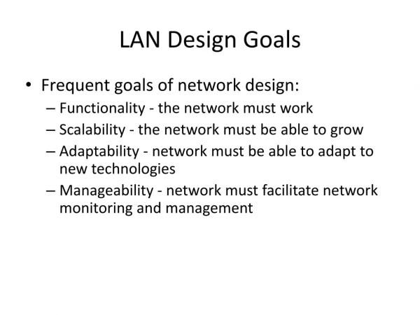
LAN Design • First step is establishing goals of the design. • This includes: • Functionality. • Scalability. • Adaptability. • Manageability.
Step 1: Analyze Requirements • Gather data - what are your customer’s needs? • What is the geographical layout? • What are the critical data and operations? • What is availability? • Network traffic loads, required throughput, future needs (growth). • What problem are you trying to solve? • Segmentation.
Step 2: Develop LAN topology • Major parts of network topology: • Layer 1: Physical Layer - cabling, and physical layout. Designed with speed and expansion capability. • Layer 2: Data Link Layer - microsegmentation with bridges and switches, limits collision domain size. • Layer 3: Network Layer - routers to limit broadcast domain. VLANs.
Layer 1 - Media and Topology • We concentrate on star/extended star topology. • In star, the MDF is the central point. • Horizontal cabling from MDF to workstations. • Catchment area (200m) within 100m Cat 5 UTP limit on horizontal cabling. • Extended star - IDFs or secondary wiring closets, gives multiple catchment areas. • Fiber optic for vertical cabling (longer runs). • Vertical cabling designed as fast link in network, at least 100 Mbps.
Layer 2 Switching • Collisions and collision domain size affect network performance. • Microsegmentation using bridges and switches can reduce collision domain size and eliminate collisions. • Switchs with one hosts per port has a collision domain of 2. • Asymmetric switches can give 10 Mbps to workstations and 100 Mbps to vertical cabling.
Migration to Higher Bandwidth • Include additional vertical cabling for future growth (higher bandwidth). • Bandwidth can be increased by changing to 100 Mbps ports on switches, and using 100 Mbps hubs. • Document speed of each cable drop.
Layer 3: Routing Implementation • Routers provide: • Both physical and logical segmentation. • Broadcast filtering. • Connectivity to WANs. • Routers vs Switches • routers limit broadcast domains, switches limit collision domains. • Routers solve problems with excessive broadcasts, can provide firewalls, security. • Routers provide built-in scaling (subnetting). • Routers are more expensive and harder to configure.
File Servers and Traffic Patterns • Applications (servers) are categorized as enterprise servers or workgroup servers. • Enterprise servers: • Support all users; e.g. email, DNS. • Located at MDF. • Workgroup servers: • Support a specific set of users. • Located at IDF, closest to specific users. • Consider faster speed for servers.
Documentation • Physical map - location of MDF, IDFs, hosts; include cutsheet (cabling runs). • Logical Network maps : • Location of MDF and IDFs, and cabling between - indicate spare cables. • IP addressing scheme - design a consistent addressing scheme throughout the network.