Steam Flow Measurement
160 likes | 212 Vues
Learn about a low-cost steam flow monitoring system using pressure drop in a steam pipeline. This self-learning presentation explains how to estimate steam flow and optimize consumption for industrial applications. Consult experts for system changes.

Steam Flow Measurement
E N D
Presentation Transcript
Steam Flow Measurement By- D K Singhal
Disclaimer This presentation is supplied as a self learning presentation, and is subjected to the condition that the author accepts no liability from the use of the same or from the techniques or information provided within the same. It is strongly recommended to consult your mechanical engineer, process engineer and other technical experts, before making any changes to the existing system.
Preface • Steam consumption is one of the significant cost factors in paper and other process industries. In absence of any steam flow metering control and optimization of steam consumption is not possible.
Available Systems • Steam flow measurement systems available in the market are very costly, and hence most of the mills cannot afford them to install. But, nothing can be controlled if it is not being monitored.
Proposed System • This must be indicated that the proposed system is of very low cost. In the proposed system, reading is taken from the instrument and with the help of calibration chart, steam flow is estimated. Accuracy may be a little lower, but benefits obtained by the proposed system may even encourage the user to purchase and install steam flow meter from a reputed supplier.
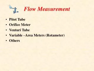
Concept • Pressure Drop across a saturated steam pipeline is a function of steam flow rate, steam pressure (and hence specific volume) and pipe diameter. • For most of the cases, steam pressure is normally kept constant, or varies within narrow limits. Pipe diameter, of course, is fixed for a particular position.
Steam Flow • The proposed system works on the basis of pressure drop in a horizontal steam pipeline, which is proportionate to square of steam flow rate. i.e. for any flow rate say pressure difference is 100mmWC, a 10% reduction in steam flow will be indicated by a reduction in pressure drop to 79mmWC. Thus, one can very easily achieve the optimum steam consumption for a particular application.
Schematic Drawing Distance for which dP is to be measured Steam Flow Pressure Gauge Gauge Glass Assly. Closed Tank Zero Level Steam Trap Baffle Plate T
About the Equipment • As indicated in figure, the tank has a partition in the center. The lower chamber is filled with water upto zero level prior to installation. Any further water coming into the tank is drained from the excess water removal line through valve and steam trap installed, as indicated in the left side of figure.
Operation • Initially, the lower chamber is filled with water. When the system is connected to steam line, steam from upstream side fills lower chamber and exerts a pressure inside gauge glass. The downstream side steam pressure fills upper chamber and tries to counterbalance the upstream pressure. The pressure drop is indicated in the gauge glass.
Initial Measurements • Distance between the two points at which the unit is connected is measured. Steam pipe diameter is also measured. The line pressure can be measured by the pressure gauge mounted on the unit, as indicated in schematic. • Gauge glass initial level is marked when there is no steam flow. Any increase in gauge glass level, thus, can be measured. • Also, the pressure can be measured by the pressure gauge mounted on the unit.
Flow Estimation • The steam flow will be proportional to the square root of gauge glass level increase, and inversely proportional to the steam pressure as indicated by the pressure gauge. • Formulae are available to calculate pressure drop in the pipeline, and depending on the distance between two points in the steam line, working pressure, pipe diameter etc., it is possible to develop a plant specific correlation.
Flow Optimization • To optimize the steam flow, just measure gauge glass level increase at a particular operating condition and pressure. • After altering process variables, if the gauge glass reading decreases, it will clearly indicate that the steam flow has reduced.
Feedback • Please send in your comments on this presentation to- D K Singhal Deveshksinghal@rediffmail.com Deveshksinghal@gmail.com Thank You.