Download
1 / 31
310 likes | 345 Vues
Comprehensive assessment of the Roamingwood Well Field in Wayne County to evaluate hazards, capture zones, and groundwater contamination risks. Recommendations for sustainable water resource management and protective measures.

E N D
Roamingwood Wellhead Protection Capture Zone Prepared by: Mr. Brian Oram, PG, MSMr. Bill Toothill, MSWilkes UniversityGeo Environmental Sciences and Environmental Engineering Department http://www.wilkes.eduhttp://www.water-research.net
The Hideout Well 3 Well 4 Well 5 Well 2 Well 6 Well 1
Roamingwood Lake – The Hideout – Project Site Photo by: Roamingwood Water and Sewer Association
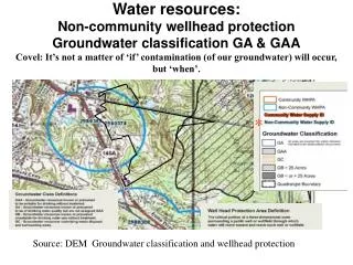
Hazard Evaluation • Drastic Analysis • Point and Non-Point Sources • Physical Features • Shallow Depth to Rock • Fractured Zones • Wetland Area
Shallow Depth to BedrockBedrock near Surface or Less than 2 feet Well 3 Well 4 Well 5 Well 6 Well 2 Well 1 Purple Areas – Shallow Depth to Bedrock
Fractured Zones Well 3 Well 4 Well 5 Well 2 Well 6 Well 1 Fracture Trace / Linear Feature
Jointing Bedding Plane Fractures Photo by: Mr. Brian Oram (2004)
Wastewater Pumping Stations Well 3 Well 4 Pump Stations Well 5 Well 2 Well 6 Well 1
Wastewater Pumping Stations Photo by: Mr. Brian Oram (2005)
Fixed RadiusMethod R=( (Q*t)/(pi *n*H))^0.5 Time Framet= 90 days, 1 year, 2 year, 5 year, 10 years For example, Well 5 t= 90 days, r = 232 feet t = 365 days, r = 466 feet t= 2 yr, r = 660 feet t= 5 yr, r = 1043 feet T = 10 yr, r = 1475 feet T = 90 days T = 10 years
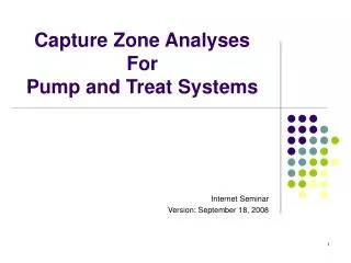
Capture Zone Analysis • Model Used – WinFlow • Steady State – Transient Flow Model • Referenced to Modflow • Reference Head – 650 feet • Gradient – 0.012 ft/d • Porosity – 7 % (trail and error) • K = 0.2 ft/d (Pump Test Data) • Storage Coefficient – 1*e^-5 (confined system) • Groundwater Discharge Rate - - 0.00026 ft/day (baseflow) • Confining Layer – 200 feet below grade • Screened – Fully Penetrating • Saturated Thickness – 500 feet • Direction of Flow – Southeast (315 degrees)
Capture Zone Analysis The capture zone analysis was completed using the WinFlow Model. The area was divided into three separate zones. The zones were defined as follows: • Zone I: Zone of Direct Influence- area where all groundwater is captured. • Zone II: Zone of Capture- area were natural flow patterns are altered and contribute to the Zone I. • Zone III: Contributes Water to the Zone II Area.
Capture ZonesSteady StateAverage PumpingRate 13 MG/Month Zone 1 Zone 3 Zone 2
Capture ZonesSteady StatePeak PumpingRate20 MG/month Zone 1 Zone 2 Zone 3
RecommendationsFor the Hideout • Maintain Chemical Inventory and Improve Hazardous Waste Storage, Management, and Transport. • Continue the STOP AND RECYCLED USED OIL FACT, Awareness Programs, other Educational Programs, and Hazardous Waste Disposal. • Prohibit the use of Underground Fuel Storage or regulate the use. • Encourage the use of water conservation devices. • Minimize Site Disturbance and Provide Maximum Lot Coverage. • Update Nutrient and Pesticide Management Plan for Golf Course. • Encourage the Use of Rainwater Capture for Irrigation Use – Rather than Potable Water Use. • Real-time monitoring of wells, including Well 6. • Additional background monitoring of select wells for major cations and anions.
High Lot Coverage – Increase Runoff and Decrease Natural Recharge Paved Driveway – Roof runoff goes to driveway and immediately to road and stormwater system.
Low Lot Coverage / Natural or Enhanced Green Areas – Decrease Runoff and Promote Natural Recharge Photos by:Brian Oram (2005) Lot Coverage – Gravel Driveway
RecommendationReach Out, Inform, and Educate Outside of the Hideout • Local Well Ordinance (Siting, Construction, and Testing) • Septic and Sludge Management Program • Public Education – school students and new residents. • Monitoring Select Private Wells within Zone II and Zone III. • Stormwater Management System that promote Recharge
Private Well Ordinance Ordinance should address: Well Siting and LocationConstruction StandardsWell Material Standards Well Grouting Initial Water Testing Image Source: Master Well Owner, Powerpoint Presentation
On-lot Disposal System Program Includes: Homeowner Education on System Operation and Maintenance Developing a Maintenance and Repair Program – Mandatory Septic Tank Pumping Developing a Septage / Sludge Management Ordinance
Individual / Community Stormwater Management Systems Example: Bioretention System for Stormwater Management
Roamingwood Wellhead Protection Capture Zone Prepared by: Mr. Brian Oram, PGMr. Bill Toothill, MSWilkes UniversityGeoEnvironmental Sciences and Engineering Departmenthttp://www.wilkes.eduhttp://www.water-research.net