Download
1 / 1
10 likes | 142 Vues
This design features a launcher with a robust structure supported by spider legs, each equipped with one nut above and one below, along with lock washers. The center body includes a storage compartment for small tools and parts to secure the spider legs. The foot pan is spacious enough to hold multiple sandbags for stability during deployment. The azimuth axis has a fold-up hinge, and the design incorporates a bubble level for precise leveling. This efficient setup allows for easy operation, compensation for wind, and accurate alignment with the azimuth references, ensuring effective launch preparations.

E N D
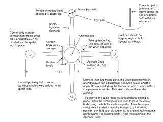
Threaded jack with one nut above spider leg and one below, both with lock washers Screw jack axis Female threaded fitting attached to spider leg Foot pan Spider leg (steel channel) Center body storage compartment holds small tools and parts such as pins to lock the spider legs in place. Foot pan should be large enough to hold several sand bags Azimuth axis Fold up hinge line. Leg secured with a pin when deployed Center body with storage Azimuth Circle marked in 5 deg steps Bubble levels ~ 14 ft Launcher has two major parts, the under pinnings which, after deployed and adjusted do not move again, and the upper structure including the launch rail which is moved to compensate for winds. This sketch shows the under pinnings. To deploy it, the spider legs are unfolded and pinned in place. Then the screw jacks are used to level the center body using the bubble levels as guides. After the upper structure is installed, the rail is brought to a horizontal position, the SkyScout placed on its tip and the rail rotated in azimuth until it is pointing north. Note the reading on the Azimuth Circle. It would probably help if some carrying handles were welded to the spider legs.