Download
1 / 83
830 likes | 1.06k Vues
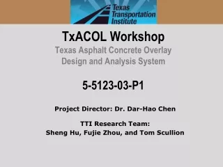
TxACOL Workshop Texas Asphalt Concrete Overlay Design and Analysis System 5-5123-03- P1. Project Director: Dr. Dar-Hao Chen TTI Research Team: Sheng Hu, Fujie Zhou, and Tom Scullion. General Information.

E N D
TxACOL WorkshopTexas Asphalt Concrete Overlay Design and Analysis System5-5123-03-P1 Project Director: Dr. Dar-Hao Chen TTI Research Team: Sheng Hu, Fujie Zhou, and Tom Scullion
General Information • Two workshops were held respectively on Aug. 25 at Paris, Tx and on Oct. 6 at Austin, Tx • More than 30 representatives from TxDOT attended • Introduction of TxACOL software, key input parameters, and related lab and field tests were presented • Attendees practiced the software step by step
Presentation Outline • Introduction • Program training and exercises • Key inputs for existing pavement and field testing • Key inputs for asphalt overlay and lab testing
Expected Learning Outcomes • Be able to perform program installation and un-installation • Be familiar with creating, editing, saving, and running a project file • Know how to design an asphalt overlay using the TxACOL program • Understand Key input parameters and the requested lab or field test
Presentation Outline • Introduction • Program training and exercises • Key inputs for existing pavement and field testing • Key inputs for asphalt overlay and lab testing
Crack propagation and reflection cracking analysis • Daily crack propagation: TxACOL Flowchart Input AC Overlay + Existing Pavement Condition Traffic Environment Models Reflection Cracking Model Rutting Model Output Cracking Data and Chart Rutting Data and Chart
TxACOL Features • M-E program • User-friendly interface • Short running time • Default values provided in the software • Traffic input is compatible to the current pavement design software FPS19W
TxACOL Features (Continued) • Pavement temperature is automatically predicted from EICM model • Rutting and cracking are analyzed simultaneously • Output is in Excel format and can be easily incorporated into electronic documents and reports
How to Install • Double click “Setup.exe” file • If this is the first installation, the following screens will appear: Choose your favorite installation folder here
Launch the Program Double click the icon or
Presentation Outline • Introduction • Program training and exercises • Key inputs for existing pavement and field testing • Key inputs for asphalt overlay and lab testing
Step 1: Create a New Project File Click this button or select the menu “File” -> “New”
Step 2: General Information Input Double Click
Step 3: Project Identification Input Double Click Similar to FPS19W
Step 4: Analysis Parameters & Criteria Input Double Click Defined by crack amount reflected to surface divided by total existing crack amount Only rutting in the new AC overlay is considered
Step 5: Traffic Input Double Click Same as FPS19W
Step 6: Climate Input Double Click
Step 7: Climate Input (Continued) Double Click
Step 8: Structure Input Double Click All commonly used overlay mix types in Texas are included
Step 10: AC Material Properties Input Level 3 Input Level 1 Input • You can import or export dynamic modulus here
Step 11: Fracture and Rutting Properties Input Fracture Properties Rutting Properties
Step 12: Existing Layer Properties Input Existing AC Existing PCC • The default values are different between JPCP and CRCP
Step 13: Base Layer Properties Input Granular Base Stabilized Base
Step 14: Subgrade Properties Input Level 2 Level 1
Step 15: Save the Project File Click the “save” icon to save all these inputs before running analysis • If it is the first time to save the project, this window will pop up and users can input project name here
Step 16: Run Analysis Click this button
Example 1 (Paris Workshop) • AC over AC • Design life: 10 years • District: Paris, Lamar • Traffic: 5 million ESALs for 20 years • Location: latitude 33°39’, longitude -95°33’, and elevation 600 ft
Example 1 (Paris Workshop) (Continued) • Layer thickness • AC overlay: 2 inches; Existing AC: 3 inches; Base: 6 inches • AC overlay property • Mix type: Type D; Binder type: PG 76-22 • Modulus Input Level: Level 3-default values • Fracture properties and Rutting properties: default values • Existing AC layer property • Transverse cracking, medium severity, cracking space: 15 ft • FWD modulus @ 77 °F: 500 ksi • Base • Type: CTB, Modulus: 200 ksi • Subgrade • Modulus: By default
Example 1 (Paris Workshop) Result Cracking Rutting
Example 1 (Austin Workshop) • Overlay Type: AC over JPCP • Design or Analysis Life: 15 years • District: Austin; County: Travis • Analysis Parameters & Criteria: Reflective Cracking Rate Limit: 50% AC Rutting: 0.5 inch • Traffic: ADT-Beginning: 20000; ADT-End: 35000; ESALs: 5.0 million; Speed: 60 mph • Weather Station: Austin/City, Tx
Example 1 (Austin Workshop ) (Continued) • Layer thickness • AC overlay: 2.5 inches; Existing JPCP: 9 inches; Base: 4 inches • AC overlay property • Mix type: Type D; Binder type: PG 76-22 • Modulus Input Level: Level 3-default values • Fracture properties and Rutting properties: default values • Existing JPCP property • Modulus: 4000 ksi, cracking space: 15 ft, LTE: 70% • Base • Type: Granular base, Modulus: 50 ksi • Subgrade • Modulus: By default
Exercise 1 • Use “New” function • Change the previous example to 2-lift overlays • The top overlay is the same Type D mix, but its thickness reduces to 1.5 inches • The bottom overlay is 1 inch CAM mix with a PG76-22 binder • All the other inputs are kept the same as Example 1
Exercise 2 • Use “Save as” function • Change the previous exercise back to one lift overlay • Select overlay mix: SMA-D with a PG76-22 binder • Keep all the other inputs the same as Example 1
Exercise 2_Hint • Use “save as” function • Click radio button “1” to remove an overlay (Remember: choose/highlight one overlay first)
Summary for Different Overlay Mixes • 2.5 inches Type D • After 52 months, Reflective Cracking Rate reaches 50%. • Rut depth reaches 0.084 inches after 15 years (180 months). 1.5 inches Type D +1 inch CAM • After 129 months, Reflective Cracking Rate reaches 50%. • Rut depth reaches 0.3inches after 15 years (180 months). 2.5 inches SMA • After 129 months, Reflective Cracking Rate reaches 50%. • Rut depth reaches 0.08 inches after 15 years (180 months).
Example 2 – Overlay Thickness Design • Overlay Type: AC over JPCP • Design Life: 10 years • District: Wichita Falls; County: Cooke • Analysis Parameters & Criteria: Reflective Cracking Rate Limit: 50% AC Rutting: 0.5 inch • Traffic: ADT-Beginning: 19350; ADT-End: 28800; ESALs: 4.5 million; Speed: 60 mph • Weather Station: Wichita Falls, Tx
Example 2 – Overlay Thickness Design (Continued) • Layer thickness • AC overlay: Unknown; Existing JPCP: 8 inches; Base: 4 inches • AC overlay property • Mix type: Type D; Binder type: PG 76-22 • Modulus Input Level: Level 3-default values • Fracture properties and Rutting properties: default values • Existing JPCP property • Modulus: 4000 ksi, joint space: 15 ft, LTE: 70% • Base • Type: Granular base, Modulus: 30 ksi • Subgrade • Modulus: By default
Trial Thicknesses During Design • Overlay thickness trial 1: 2 inches • Overlay thickness trial 2: 4 inches • After 15 months, Reflective Cracking Rate reaches 50%. • Rut depth reaches 0.05 inches after 15 years (180 months). • After 162 months, Reflective Cracking Rate reaches 50%. • Rut depth reaches 0.077 inches after 15 years (180 months).
Trial Thicknesses During Design (Continued) • Overlay thickness trial 3: 3.5 inches • Obviously for all these cases, the rutting problem is not significant. To meet the 10 years design life requirement, a 4 inches overlay is recommended • After 100 months, Reflective Cracking Rate reaches 50%. • Rut depth reaches 0.07 inches after 15 years (180 months).
Exercise 3 • Change the existing JPCP’s LTE to 50% • Keep the other inputs the same as Example 2 • The recommended overlay thickness=?
Answer to Exercise 3 5 inches • Trial 1: 4 inches, 69 months • Trial 2: 5 inches, 148 months • Trial 3: 4.5 inches, 105 months
Tips and Reminders • Accept default values if you don’t have specific test results • Use climatic interpolation function when there is no existing weather station available in this area • Use “save as” to reduce some input work • Save the project file before clicking “Analysis” button • Do not move or rename the project file manually
Presentation Outline • Introduction • Program training and exercises • Key inputs for existing pavement and field testing • Key inputs for overlays and lab test
Key Input Parameters for Existing Pavements • Existing pavements • 1) Layer modulus and 2) Joints/cracks LTE • Field testing • FWD • RDD
JPCP Pavement Evaluation • For Layer modulus backcalculation • center slab • 30 drops per section (max spacing: 0.1 mile) • For LTE • joint measurements • FWD • RDD
FWD Backcalculated Modulus • In Texas, “MODULUS 6.0” is commonly used for modulus backcalculation
FWD Based LTE at Joints/Cracks FWD Load FWD Load W1c W2c W2j W1j LTE = (W2j/W1j)/ (W2c/W1c) Near the slab center Near the joint/crack