Chapter 4 Object Oriented Analysis
OO Analysis Overview. 4.1 OO Analysis Overview. Understanding Analysis Analysis Versus Design Object Oriented Analysis Three ways to do Object Oriented Analysis. Understanding Analysis. In software engineering, analysis is the process of converting the user requirements to system specificatio

Chapter 4 Object Oriented Analysis
E N D
Presentation Transcript
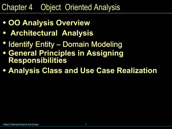
1. Chapter 4 Object Oriented Analysis OO Analysis Overview
Architectural Analysis
Identify Entity � Domain Modeling
General Principles in Assigning Responsibilities
Analysis Class and Use Case Realization
3. 4.1 OO Analysis Overview Understanding Analysis
Analysis Versus Design
Object Oriented Analysis
Three ways to do Object Oriented Analysis
4. Understanding Analysis In software engineering, analysis is the process of converting the user requirements to system specification
system means the software to be developed.
System specification, also known as the logic structure, is the developer�s view of the system.
Function-oriented analysis � concentrating on the decomposition of complex functions to simply ones.
Object-oriented analysis � identifying objects and the relationship between objects.
5. Understanding Analysis The goal in Analysis is to understand the problem
and to begin to develop a visual model of what you are trying to build, independent of implementation and technology concerns.
Analysis focuses on translating the functional requirements into software concepts.
The idea is to get a rough cut at the objects that comprise our system, but focusing on behavior (and therefore encapsulation).
We then move very quickly, nearly seamlessly into �design� and the other concerns.
6. Analysis Versus Design Analysis
Focus on understanding the problem
Idealized design
Behavior
System structure
Functional requirements
A small model Design
Focus on understanding the solution
Operations and Attributes
Performance
Close to real code
Object lifecycles
Non-functional requirements
A large model
7. Object Oriented Analysis Identifying objects:
Using concepts, CRC cards, stereotypes, etc.
Organising the objects:
classifying the objects identified, so similar objects can later be defined in the same class.
Identifying relationships between objects:
this helps to determine inputs and outputs of an object.
Defining operations of the objects:
the way of processing data within an object.
Defining objects internally:
information held within the objects.
8. Three ways to do Object Oriented Analysis Conceptual model (Larman)
Produce a �light� class diagram.
CRC cards (Beck, Cunningham)
Index cards and role playing.
Analysis model with stereotypes (Jacobson)
Boundaries, entities, control.
10. 4.2 Architectural Analysis Architectural Analysis
Identification and Analysis of Architectural Factors
Summary of Themes in Architectural Analysis
11. Architectural Analysis Architectural analysis is concerned with the identification and resolution of the system's non-functional (for example, quality) requirements, in the context of the functional requirements
In the UP, the term encompasses both architectural investigation (identification) and architectural design (resolution)
12. Architectural Analysis - Purpose To define a candidate architecture for the system, based on experience gained from similar systems or in similar problem domains.
To define the architectural patterns, key mechanisms and modeling conventions for the system.
To define the reuse strategy
To provide input to the planning process
13. Design Model Overview
14. Common Steps in Architectural Analysis Identify and analyze the non-functional requirements that have an impacton the architecture.
Functional requirements are also relevant (especially in terms of variability or change), but the non-functional are given thorough attention.
In general, all these may be called architectural factors (also known as the architectural drivers)
For those requirements with a significant architectural impact, analyze alternatives and create solutions that resolve the impact.
These are architectural decisions.
15. Identification and Analysis of Architectural Factors Architectural Factors
Quality Scenarios
Factor Table
Factors and UP Artifacts
16. Quality Scenarios When defining quality requirements during architectural factor analysis, quality scenarios are recommended,
as they define measurable (or at least observable) responses, and thus can be verified.
It is not much use to vaguely state "the system will be easy to modify" without some measure of what that means.
Quantifying some things, such as performance goals and mean time between failure, are well known practices, but quality scenarios extend this idea and encourages recording all (or at least, most) factors as measurable statements.
Quality scenarios are short statements of the form <stimulus> <measurable response>; for example:
When the completed sale is sent to the remote tax calculator to add the taxes, the result is returned within 2 seconds "most" of the time, measured in a production environment under "average" load conditions.
When a bug report arrives from a NextGen beta test volunteer, reply with a phone call within 1 working day.
17. Factor Table Most architectural methods advocate creating a table or tree with variations of the following information.
The following style shown in Table is called a factor table,
which in the UP is part of the Supplementary Specification
18. Factors and UP Artifacts The central functional requirements repository in the UP are the use cases, and they, along with the Vision and Supplementary Specification, are an important source of inspiration when creating a factor table.
In the use cases, the Special Requirements,Technology Variations, and Open Issues should be reviewed, and their implied or explicit architectural factors consolidated in the Supplementary Specification.
19. Example: Partial NextGen POS Architectural Factor Table
20. Summary of Themes in Architectural Analysis "architectural" concerns are especially related to nonfunctional requirements,
and include an awareness of the business or market context of the application.
At the same time, the functional requirements (for example, processing sales) cannot be ignored; they provide the context within which these concerns must be resolved.
Further,identification of their variability is architecturally significant.
architectural concerns involve system-level,large-scale, and broad problems whose resolution usually involves large-scale or fundamental design decisions
for example, the choice of�or even use of�an application server.
interdependencies and trade-offs.
For example, improved security may affect performance or usability, and most choices affect cost.
the generation and evaluation of alternative solutions
21. Architectural Information in the UP Artifacts The architectural factors (for example, in a factor table) are recorded in the Supplementary Specification.
23. 4.3 Identify Entity � Domain Modeling Visualizing Concepts
Adding Associations
Adding Attributes
Modeling Generalization
Refining the Domain Model
24. VISUALIZING CONCEPTS Domain Models
Conceptual Class Identification
Domain Modeling Guidelines
Resolving Similar Conceptual Classes
Modeling the Unreal world
Specification Conceptual Classes
UML Notation v.s. Methodology
Lowering the Representational Gap
Domain Models within the UP
25. Domain Models A domain model is a representation of real-world conceptual classes
not a representation of software components.
not a set of diagrams describing software classes,
not software objects with responsibilities.
A domain model is a visual representation of conceptual classes or real-world objects in a domain of interest [MO95, Fowler96]
They have also been called conceptual models, domain object models, and analysis object models.
The UP defines a Domain Model as one of the artifacts that may be created in the Business Modeling discipline.
26. Domain Models Using UML notation, a domain model is illustrated with a set of class diagrams in which no operations are defined. It may show:
domain objects or conceptual classes
associations between conceptual classes
attributes of conceptual classes
27. Domain Models The domain model illustrates conceptual classes or vocabulary in the domain.
Domain Models are not models of software components. The following elements are not suitable in a domain model:
Software artifacts, such as a window or a database, unless the domain being modeled is of software concepts, such as a model of graphical user interfaces.
Responsibilities or methods.
28. Domain Models The domain model illustrates conceptual classes or vocabulary in the domain.
Informally, a conceptual class is an idea, thing, or object.
More formally, a conceptual class may be considered in terms of its symbol, intension, and extension[MO95].
Symbol�words or images representing a conceptual class.
Intension�the definition of a conceptual class.
Extension�the set of examples to which the conceptual class applies.
29. Domain Models Software problems can be complex;
Decomposition (divide-and-conquer) is a common strategy to deal with this complexity by division of the problem space into comprehensible units.
In structured analysis, the dimension of decomposition is by processes or functions.
However, in object-oriented analysis, the dimension of decomposition is fundamentally by things or entities in the domain.
A central distinction between object-oriented and structured analysis is: division by conceptual classes (objects) rather than division by functions.
A primary analysis task is to identify different concepts in the problem domain and document the results in a domain model
30. Conceptual Class Identification A useful guideline in identifying conceptual classes:
It is better to overspecify a domain model with lots of fine-grained conceptual classes than to underspecify it.
Strategies to Identify Conceptual Classes.
Use a conceptual class category list.
Finding conceptual classes with Noun Phrase Identification
Another excellent technique for domain modeling is the use of analysis patterns, which are existing partial domain models created by experts,
using published resources such as Analysis Patterns [Fowler96] and Data Model Patterns[Hay96].
31. Domain Modeling Guidelines How to Make a Domain Model
1. List the candidate conceptual classes using the Conceptual Class Category List and noun phrase identification techniques related to the current requirements under consideration.
2. Draw them in a domain model.
3. Add the associations necessary to record relationships for which there is a need to preserve some memory.
4. Add the attributes necessary to fulfill the information requirements.
On Naming and Modeling Things
use the vocabulary of the domain when naming conceptual classes and attributes.
For example, if developing a model for a library, name the customer a "Borrower" or "Patron"�the terms used by the library staff.
a domain model may exclude conceptual classes in the problem domain not pertinent to the requirements.
For example, we may exclude Pen and PaperBag from our domain model (for the current set of requirements) since they do not have any obvious noteworthy role.
the domain model should exclude things not in the problem domain under consideration.
32. Domain Modeling Guidelines A Common Mistake in Identifying Conceptual Classes
Perhaps the most common mistake when creating a domain model is to represent something as an attribute when it should have been a concept.
A rule of thumb to help prevent this mistake is:
If we do not think of some conceptual class X as a number or text in the real world, X is probably a conceptual class, not an attribute.
As an example, should store be an attribute of Sale, or a separate conceptual class Store?
In the real world, a store is not considered a number or text - the term suggests a legal entity, an organization, and something occupies space. Therefore, Store should be a concept.
As another example, consider the domain of airline reservations. Should destination be an attribute of Flight, or a separate conceptual class Airport?
In the real world, a destination airport is not considered a number or text�it is a massive thing that occupies space. Therefore, Airport should be a concept.
33. Resolving Similar Conceptual Classes As a example, in the domain model, should the symbol Register be used instead of POST?
POST" is a term familiar in the territory, so it is a useful symbol from the point of view of familiarity and communication.
By the goal of creating models that represent abstractions and are implementation independent, Register is appealing and useful.
As a rule of thumb, a domain model is not absolutely correct or wrong, but more or less useful; it is a tool of communication.
34. Modeling the Unreal world Some software systems are for domains that find very little analogy in natural or business domains;
software for telecommunications is an example.
It is still possible to create a domain model in these domains, but it requires a high degree of abstraction and stepping back from familiar designs.
For example, here are some candidate conceptual classes related to a telecommunication switch:
Message, Connection, Port, Dialog, Route, Protocol.
35. Specification or Description Conceptual Classes Specifications or descriptions about other things.
36. Specification or Description Conceptual Classes Add a specification or description conceptual class (for example, ProductSpecification) when:
There needs to be a description about an item or service, independent of the current existence of any examples of those items or services.
Deleting instances of things they describe (for example, Item) results in a loss of information that needs to be maintained, due to the incorrect association of information with the deleted thing.
It reduces redundant or duplicated information.
37. UML Notation v.s. Methodology The UML simply describes raw diagram types, such as class diagrams and sequence diagrams. It does not superimpose a method or modeling perspective on these.
Rather, a process (such as the UP) applies raw UML in the context of methodologist-defined models.
Three perspectives and types of models:
Conceptual perspective
the diagrams are interpreted as describing things in the real world or domain of interest.
Specification perspective
the diagrams are interpreted as describing software abstractions or
components with specifications and interfaces, but no commitment to a particular implementation (for example, not specifically a class in C# or Java).
Implementation perspective
the diagrams are interpreted as describing software implementations in a particular technology and language (such as Java).
38. Lowering the Representational Gap The Domain Model provides a visual dictionary of the domain vocabulary and concepts from which to draw inspiration for the naming of some things in the software design.
In object design and programming it is common to create software classes whose names and information is inspired from the real world domain.
39. Domain Models within the UP Domain models are not strongly motivated in inception,
since inception's purpose is not to do a serious investigation, but rather to decide if the project is worth deeper investigation in an elaboration phase.
The Domain Model is primarily created during elaboration iterations,
when the need is highest to understand the noteworthy concepts and map some to software classes during design work.
40. Domain Models within the UP The UP Domain Model is an official variation of the less common UP Business Object Model (BOM).
[The UP BOM] serves as an abstraction of how business workers and business entities need to be related and how they need to collaborate in order to perform the business. [RUP]
The BOM is represented with several different diagrams (class, activity, and sequence) that illustrate how the entire enterprise runs (or should run).
It is most useful if doing enterprise-wide business process engineering,
but that is a less common activity than creating a single software application.
Consequently, the UP defines the Domain Model as the more commonly created subset artifact or specialization of the BOM.
41. Domain Models within the UP Artifact influence emphasizing the Domain Model
42. Adding Association Associations
The UML Association Notation
Finding Associations
Association Guidelines
Roles
How Detailed Should Associations Be?
Naming Associations
Multiple Associations Between Two Types
Associations and Implementation
Example
43. Associations An association is a relationship between types (or more specifically, instances of those types) that indicates some meaningful and interesting connection
In the UML associations are defined as "the semantic relationship between two or more classifiers that involve connections among their instances.�
Criteria for Useful Associations
Associations for which knowledge of the relationship needs to be preserved for some duration ("need-to-know" associations).
Associations derived from the Common Associations List.
44. The UML Association Notation An association is represented as a line between classes with an association name.
The association is inherently bidirectional, meaning that from instances of either class, logical traversal to the other is possible.
This traversal is purely abstract; it is not a statement about connections between software entities.
The ends of an association may contain a multiplicity expression indicating the numerical relationship between instances of the classes.
An optional "reading direction arrow" indicates the direction to read the association name; it does not indicate direction of visibility or navigation.
45. Finding Associations Start the addition of associations by using the Common Associations List
It contains common categories that are usually worth considering.
Here are some high-priority association categories that are invariably useful to include in a domain model:
A is a physical or logical part of B.
A is physically or logically contained in/on B.
A is recorded in B.
46. Association Guidelines Focus on those associations for which knowledge of the relationship needs to be preserved for some duration ("need-to-know" associations).
It is more important to identify conceptual classes than to identify associations.
Too many associations tend to confuse a domain model rather than illuminate it. Their discovery can be time-consuming, with marginal benefit.
Avoid showing redundant or derivable associations.
47. Roles Each end of an association is called a role. Roles may optionally have:
name
multiplicity expression
navigability
48. Naming Associations Name an association based on a TypeName-VerbPhrase-TypeName format where the verb phrase creates a sequence that is readable and meaningful in the model context.
49. Multiple Associations Between Two Types Two types may have multiple associations between them;
this is not uncommon.
50. Associations and Implementation During domain modeling, an association is not a statement about data flows, instance variables, or object connections in a software solution;
it is a statement that a relationship is meaningful in a purely conceptual sense�in the real world.
51. Example The following sample of associations is justified in terms of a need-to-know.
It is based on the use cases currently under consideration.
52. Example-Applying the Category of Associations Checklist
53. Example
54. Example
55. Adding Attributes Attributes VS. Associations
Non-primitive Data Type Classes
No Attributes as Foreign Keys
Modeling Attribute Quantities and Units
56. Attributes VS. Associations The attributes in a domain model should preferably be simple attributes or data types.
57. Non-primitive Data Type Classes If the attribute class is a data type, it may be shown in the attribute box.
58. Design Creep: No Attributes as Foreign Keys Attributes should not be used to relate conceptual classes in the domain model.
The most common violation of this principle is to add a kind of foreign key attribute, as is typically done in relational database designs, in order to associate two types.
59. Modeling Attribute Quantities and Units Most numeric quantities should not be represented as plain numbers.
60. Modeling Generalization New Concepts for the Domain Model
Generalization
Defining Conceptual Superclasses and Subclasses
Abstract Conceptual Classes
Modeling Changing States
61. Category Concepts List
62. Noun Phrase Identification from the Use Cases
63. Noun Phrase Identification from the Use Cases
64. generalization-specialization class hierarchy The concepts CashPayment, CreditPayment, and Check Payment are all very similar.
65. Conceptual Subclass Definition Conformance
66. Conceptual Subclass Set Conformance
67. When to Define a Conceptual Subclass?
68. What Is a Correct Conceptual Subclass?
69. Example subclass partitions
70. NextGen POS Conceptual Class Hierarchies
71. NextGen POS Conceptual Class Hierarchies
72. Concepts too fine grained?
73. Concepts too fine grained?
74. Abstract Conceptual Classes
75. Abstract Class Notation in the UML
76. Modeling Changing States
77. Refining the domain model Association Classes
Aggregation and Composition
Roles as Concepts vs. Roles in Associations
Qualified Associations
Reflexive Associations
Using Packages to Organize the Domain Model
78. Association Classes
79. Association Classes
80. Aggregation A special form of association that models a whole-part relationship between an aggregate (the whole) and its parts An aggregation is a stronger form of relationship where the relationship is between a whole and its parts. The aggregate has an aggregation association to the its constituent parts. A hollow diamond is attached to the end of an association path on the side of the aggregate (the whole) to indicate aggregation.
Since aggregation is a special form of association, the use of multiplicity, roles, navigation, etc. is the same as for association.
Sometimes, a class may be aggregated with itself. This does not mean that an instance of that class is composed of itself (this would be silly), it means that one instance if the class is an aggregate composed of other instances of the same class.
Some situations where aggregation may be appropriate:
An object is physically composed of other objects (e.g. car being physically composed of an engine and four wheels).
An object is a logical collection of other objects (e.g., a family is a collection of parents and children).
An object physically contains other objects (e.g., an airplane physically contains a pilot).
In the above example, the relationship from Student to Schedule is modeled as an aggregation because a Schedule is inherently tied to a particular Student. A Schedule outside of the context of a Student makes no sense in a Course Registration System. An aggregation is a stronger form of relationship where the relationship is between a whole and its parts. The aggregate has an aggregation association to the its constituent parts. A hollow diamond is attached to the end of an association path on the side of the aggregate (the whole) to indicate aggregation.
Since aggregation is a special form of association, the use of multiplicity, roles, navigation, etc. is the same as for association.
Sometimes, a class may be aggregated with itself. This does not mean that an instance of that class is composed of itself (this would be silly), it means that one instance if the class is an aggregate composed of other instances of the same class.
Some situations where aggregation may be appropriate:
An object is physically composed of other objects (e.g. car being physically composed of an engine and four wheels).
An object is a logical collection of other objects (e.g., a family is a collection of parents and children).
An object physically contains other objects (e.g., an airplane physically contains a pilot).
In the above example, the relationship from Student to Schedule is modeled as an aggregation because a Schedule is inherently tied to a particular Student. A Schedule outside of the context of a Student makes no sense in a Course Registration System.
81. Composition A form of aggregation with strong ownership and coincident lifetimes
The parts cannot survive the whole/aggregate Composition is a form of aggregation with strong ownership and coincident lifetimes of the part with the aggregate. The whole �owns� the part and is responsible for the creation and destruction of the part. The part is removed when the whole is removed. The part may be removed (by the whole) before the whole is removed.
A solid filled diamond is attached to the end of an association path (on the �whole side�) to indicate composition.
In some cases, composition can be identified as early as analysis, but more often it is not until design that such decisions can be made confidently. That is why composition is introduced here rather than in Use-Case Analysis.Composition is a form of aggregation with strong ownership and coincident lifetimes of the part with the aggregate. The whole �owns� the part and is responsible for the creation and destruction of the part. The part is removed when the whole is removed. The part may be removed (by the whole) before the whole is removed.
A solid filled diamond is attached to the end of an association path (on the �whole side�) to indicate composition.
In some cases, composition can be identified as early as analysis, but more often it is not until design that such decisions can be made confidently. That is why composition is introduced here rather than in Use-Case Analysis.
82. Roles as Concepts vs. Roles in Associations
83. Qualified Associations
84. Reflexive Associations
85. Using Packages to Organize the Domain Model
86. Using Packages to Organize the Domain Model
87. Using Packages to Organize the Domain Model
88. Using Packages to Organize the Domain Model
89. Using Packages to Organize the Domain Model
91. 4.4 General Principles in Assigning Responsibilities Responsibilities
Responsibility-Driven Design
CRC Cards
GRASP
92. Responsibilities The UML defines a responsibility as "a contract or obligation of a classifier"
A knowing or doing service or group of services provided by an element (such as a class or subsystem);
A responsibility embodies one or more of the purposes or obligations of an element.
A popular way of thinking about the design of software objects and also larger-scale components is in terms of responsibilities, roles, and collaborations.
93. Responsibilities Doing responsibilities of an object include:
doing something itself, such as creating an object or doing a calculation
initiating action in other objects
controlling and coordinating activities in other objects
Knowing responsibilities of an object include:
knowing about private encapsulated data
knowing about related objects
knowing about things it can derive or calculate
For example
"a Sale is responsible for creating SalesLineItems" (a doing),
"a Sale is responsible for knowing its total" (a knowing).
94. Responsibility-Driven Design (RDD) A general metaphor for thinking about OO software design
RDD leads to viewing an OO analysis & design as a community of collaborating responsible objects.
RDD also includes the idea of collaboration.
Responsibilities are implemented by means of methods that either act alone or collaborate with other methods and objects.
In RDD, Responsibilities are related to the obligations or behavior of an object in terms of its role.
95. CRC cards CRC stands for Class-Responsibility-Collaborator. They look like:
one per class, which shows its responsibilities and with which other class(es) it must collaborate in order to fulfill each responsibility.
Write a brief description of the class on the back of the card.
CRC cards are useful in detecting responsibilities of objects (developed by Kent Beck and Ward Cunningham).
96. CRC Cards - Example In this example, class Foo must collaborate with (send messages to) classes X & Y in order to fulfill its responsibility to be able to �do something.�
97. GRASP : General Principles in Assigning Responsibilities Creator
Information Expert
Low Coupling
Controller
High Cohesion
98. GRASP - Creator Problem:
Who creates an A?
Solution
Assign class B the responsibility to create an instance of class A if one of these is true (the more the better):
B "contains" or compositely aggregates A.
B records A.
B closely uses A.
B has the initializing data for A.
99. GRASP - Information Expert Problem:
What is a basic principle by which to assign responsibilities to objects?
Solution
Assign a responsibility to the class that has the information needed to fulfill it.
100. GRASP - Low Coupling Problem:
How to reduce the impact of change?
Solution
Assign responsibilities so that (unnecessary) coupling remains low.
Use this principle to evaluate alternatives.
101. GRASP - Controller Problem:
What first object beyond the UI layer receives and coordinates ("controls") a system operation?
Solution
Assign the responsibility to an object representing one of these choices:
Represents the overall "system," a "root object," a device that the software is running within, or a major subsystem (these are all variations of a facade controller).
Represents a use case scenario within which the system operation occurs (a use case or session controller)
102. GRASP - Low Coupling Problem:
How to keep objects focused, understandable, and manageable, and as a side effect, support Low Coupling?
Solution
Assign responsibilities so that cohesion remains high.
Use this to evaluate alternatives.
104. 4.5 Analysis Class and Use Case Realization What is an Analysis Class?
Use Case Realization
105. What is an Analysis Class? Analysis classes represent an early conceptual model for �things in the system which have responsibilities and behavior�.
Analysis classes are used to capture a �first-draft�, rough-cut of the object model of the system.
Analysis classes handle primarily functional requirements.
They model objects from the problem domain.
106. What is an Analysis Class? There are three aspects of the system that are likely to change:
the boundary between the system and its actors,
the information the system uses, and
the control logic of the system.
107. What is an Analysis Class? In an effort to isolate the parts of the system that will change, different types of analysis classes are identified with a �canned� set of responsibilities:
boundary,
entity and
control classes.
108. What is an Analysis Class?
109. Analysis Classes: A First Step Towards Executables
110. What is a Boundary Class? Intermediates between the interface and something outside the system
Several Types
User interface classes
System interface classes
Device interface classes
One boundary class per actor/use case pair
A boundary class intermediates between the interface and something outside the system. Boundary class insulate the system from changes in the surroundings (e.g. changes in interfaces to other systems, changes in user requirements, etc.), keeping these changes from affecting the rest of the system.
A system may have several types of boundary classes:
User interface classes - Classes which intermediate communication with human users of the system.
System interface classes - Classes which intermediate communication with other systems. A boundary class which communicates with an external system is responsible for managing the dialogue with the external system; it provides the interface to that system for the system being built.
Device interface classes - Classes which provide the interface to devices which detect external events. These boundary classes capture the responsibilities of the device or sensor.
One recommendation for the initial identification of boundary classes is one boundary class per actor/use-case pair.
111. The Role of a Boundary Class A boundary class is used to model interaction between the system's surroundings and its inner workings. Such interaction involves transforming and translating events and noting changes in the system presentation (such as the interface).
Boundary classes model the parts of the system that depend on its surroundings. They make it easier to understand the system because they clarify the system's boundaries and aid design by providing a good point of departure for identifying related services. For example, if you identify a printer interface early in the design, you will realize that you must also model the formatting of printouts.
Because boundary classes are used between Actors and the internal system�s working (Actors can only communicate with boundary classes) they insulate external forces from internal mechanisms and vice versa. Thus, changing the GUI or communication protocol should mean changing only the boundary classes, not the entity and control classes.
A boundary object (an instance of a boundary class) can outlive a use-case instance if, for example, it must appear on a screen between the performance of two use cases. Normally, however, boundary objects live only as long as the use-case instance. A boundary class is used to model interaction between the system's surroundings and its inner workings. Such interaction involves transforming and translating events and noting changes in the system presentation (such as the interface).
Boundary classes model the parts of the system that depend on its surroundings. They make it easier to understand the system because they clarify the system's boundaries and aid design by providing a good point of departure for identifying related services. For example, if you identify a printer interface early in the design, you will realize that you must also model the formatting of printouts.
Because boundary classes are used between Actors and the internal system�s working (Actors can only communicate with boundary classes) they insulate external forces from internal mechanisms and vice versa. Thus, changing the GUI or communication protocol should mean changing only the boundary classes, not the entity and control classes.
A boundary object (an instance of a boundary class) can outlive a use-case instance if, for example, it must appear on a screen between the performance of two use cases. Normally, however, boundary objects live only as long as the use-case instance.
112. Example: Finding Boundary Classes One boundary class per actor/use case pair The goal of analysis is to form a good picture of how the system is composed, not to design every last detail. In other words, identify boundary classes only for phenomena in the system or for things mentioned in the flow of events of the use-case realization.
Consider the source for all external events and make sure there is a way for the system to detect these events.
One recommendation for the initial identification of boundary classes is one boundary class per actor/use-case pair. This class can be viewed as having responsibility for coordinating the interaction with the actor. This may be refined as a more detailed analysis is performed. This is particularly true for window-based GUI applications where there is typically one boundary class for each window, or one for each dialog.
In the above example:
The RegisterForCoursesForm contains a Student's "schedule-in-progress". It displays a list of Course Offerings for the current semester from which the Student may select courses to be added to his/her Schedule.
The CourseCatalogSystem interfaces with the legacy system that provides the unabridged catalog of all courses offered by the university. This class replaces the CourseCatalog abstraction originally identified in Architectural Analysis.The goal of analysis is to form a good picture of how the system is composed, not to design every last detail. In other words, identify boundary classes only for phenomena in the system or for things mentioned in the flow of events of the use-case realization.
Consider the source for all external events and make sure there is a way for the system to detect these events.
One recommendation for the initial identification of boundary classes is one boundary class per actor/use-case pair. This class can be viewed as having responsibility for coordinating the interaction with the actor. This may be refined as a more detailed analysis is performed. This is particularly true for window-based GUI applications where there is typically one boundary class for each window, or one for each dialog.
In the above example:
The RegisterForCoursesForm contains a Student's "schedule-in-progress". It displays a list of Course Offerings for the current semester from which the Student may select courses to be added to his/her Schedule.
The CourseCatalogSystem interfaces with the legacy system that provides the unabridged catalog of all courses offered by the university. This class replaces the CourseCatalog abstraction originally identified in Architectural Analysis.
113. Guidelines: Boundary Class User Interface Classes
Concentrate on what information is presented to the user
Do NOT concentrate on the UI details
System and Device Interface Classes
Concentrate on what protocols must be defined
Do NOT concentrate on how the protocols will be implemented When identifying and describing analysis classes, be careful not too spend too much time on the details. Analysis classes are meant to be a first cut at the abstractions of the system. They help to clarify the understanding of the problem to be solved, and represent an attempt at an idealized solution (analysis has been called �idealized design�).
User Interface Classes: Boundary classes may be used as �holding places� for GUI classes. The objective is not to do GUI design in this analysis, but to isolate all environment-dependent behavior. The expansion, refinement and replacement of these boundary classes with actual user interface classes (probably derived from purchased UI libraries) is a very important activity of Class Design and will be discussed in the Class Design module. Sketches or screen dumps from a user-interface prototype may have been used during the Requirements workflow to illustrate the behavior and appearance of the boundary classes. These may be associated with a boundary class. However, only model the key abstractions of the system; do not model every button, list and widget in the GUI.
System and Device Interface Classes: If the interface to an existing system or device is already well-defined, the boundary class responsibilities should be derived directly from the interface definition. If there is a working communication with the external system or device, make note of it for later reference during design.When identifying and describing analysis classes, be careful not too spend too much time on the details. Analysis classes are meant to be a first cut at the abstractions of the system. They help to clarify the understanding of the problem to be solved, and represent an attempt at an idealized solution (analysis has been called �idealized design�).
User Interface Classes: Boundary classes may be used as �holding places� for GUI classes. The objective is not to do GUI design in this analysis, but to isolate all environment-dependent behavior. The expansion, refinement and replacement of these boundary classes with actual user interface classes (probably derived from purchased UI libraries) is a very important activity of Class Design and will be discussed in the Class Design module. Sketches or screen dumps from a user-interface prototype may have been used during the Requirements workflow to illustrate the behavior and appearance of the boundary classes. These may be associated with a boundary class. However, only model the key abstractions of the system; do not model every button, list and widget in the GUI.
System and Device Interface Classes: If the interface to an existing system or device is already well-defined, the boundary class responsibilities should be derived directly from the interface definition. If there is a working communication with the external system or device, make note of it for later reference during design.
114. What is an Entity Class? Key abstractions of the system Entity objects represent the key concepts of the system being developed. Entity classes provide another point of view from which to understand the system because they show the logical data structure. Knowing the data structure can help you understand what the system is supposed to offer its users.
Frequent sources of inspiration for entity classes are the:
Glossary (developed during requirements)
Business-domain model (developed during business modeling, if business modeling has been performed)
Use-case flow of events (developed during requirements)
Key abstractions (identified in Architectural Analysis)
As mentioned earlier, sometimes there is a need to model information about an actor within the system. This is not the same as modeling the actor (actors are external. by definition). In this case, the information about the actor is modeled as an entity class. These classes are sometimes called �surrogates�.
Entity objects represent the key concepts of the system being developed. Entity classes provide another point of view from which to understand the system because they show the logical data structure. Knowing the data structure can help you understand what the system is supposed to offer its users.
Frequent sources of inspiration for entity classes are the:
Glossary (developed during requirements)
Business-domain model (developed during business modeling, if business modeling has been performed)
Use-case flow of events (developed during requirements)
Key abstractions (identified in Architectural Analysis)
As mentioned earlier, sometimes there is a need to model information about an actor within the system. This is not the same as modeling the actor (actors are external. by definition). In this case, the information about the actor is modeled as an entity class. These classes are sometimes called �surrogates�.
115. The Role of an Entity Class Entity classes represent stores of information in the system. They are typically used to represent the key concepts that the system manages. Entity objects (instances of entity classes) are used to hold and update information about some phenomenon, such as an event, a person, or some real-life object. They are usually persistent, having attributes and relationships needed for a long period, sometimes for the lifetime of the system.
The main responsibilities of entity classes are to store and manage information in the system.
An entity object is usually not specific to one use-case realization and sometimes it�s not even specific to the system itself. The values of its attributes and relationships are often given by an actor. An entity object may also be needed to help perform internal system tasks. Entity objects can have behavior as complicated as that of other object stereotypes. However, unlike other objects, this behavior is strongly related to the phenomenon the entity object represents. Entity objects are independent of the environment (the actors).Entity classes represent stores of information in the system. They are typically used to represent the key concepts that the system manages. Entity objects (instances of entity classes) are used to hold and update information about some phenomenon, such as an event, a person, or some real-life object. They are usually persistent, having attributes and relationships needed for a long period, sometimes for the lifetime of the system.
The main responsibilities of entity classes are to store and manage information in the system.
An entity object is usually not specific to one use-case realization and sometimes it�s not even specific to the system itself. The values of its attributes and relationships are often given by an actor. An entity object may also be needed to help perform internal system tasks. Entity objects can have behavior as complicated as that of other object stereotypes. However, unlike other objects, this behavior is strongly related to the phenomenon the entity object represents. Entity objects are independent of the environment (the actors).
116. Example: Finding Entity Classes Use use-case flow of events as input
Key abstractions of the use case
Traditional, filtering nouns approach
Underline noun clauses in the use-case flow of events
Remove redundant candidates
Remove vague candidates
Remove actors (out of scope)
Remove implementation constructs
Remove attributes (save for later)
Remove operations
Taking the use case flow of events as input, underline the noun phrases in the flow of events. These form the initial candidate list of analysis classes.
Next, go through a series of filtering steps where some candidate classes are eliminated. This is necessary due to the ambiguity of the English language. The result of the filtering exercise is a refined list of candidate entity classes. While the filtering approach does add some structure to what could be an ad-hoc means of identifying classes, people generally filter as they go rather than blindly accepting all nouns and then filtering.Taking the use case flow of events as input, underline the noun phrases in the flow of events. These form the initial candidate list of analysis classes.
Next, go through a series of filtering steps where some candidate classes are eliminated. This is necessary due to the ambiguity of the English language. The result of the filtering exercise is a refined list of candidate entity classes. While the filtering approach does add some structure to what could be an ad-hoc means of identifying classes, people generally filter as they go rather than blindly accepting all nouns and then filtering.
117. Example: Candidate Entity Classes Register for Courses (Create Schedule) The following are the definitions for each of the classes shown in the above diagram:
CourseOffering - A specific offering for a course, including days of the week and times.
Schedule - The courses a student has selected for the current semester.
Student - A person enrolled in classes at the university.
As mentioned earlier, sometimes there is a need to model information about an actor within the system. This is not the same as modeling the actor (actors are external. by definition). These classes are sometimes called �surrogates�.
For example, a course registration system maintains information about the student which is independent of the fact that the student also plays a role as an actor in the system. This information about the student is stored in a �Student� class that is completely independent of the �actor� role the student plays. The Student class will exist whether or not the student is an actor to the system.
The following are the definitions for each of the classes shown in the above diagram:
CourseOffering - A specific offering for a course, including days of the week and times.
Schedule - The courses a student has selected for the current semester.
Student - A person enrolled in classes at the university.
As mentioned earlier, sometimes there is a need to model information about an actor within the system. This is not the same as modeling the actor (actors are external. by definition). These classes are sometimes called �surrogates�.
For example, a course registration system maintains information about the student which is independent of the fact that the student also plays a role as an actor in the system. This information about the student is stored in a �Student� class that is completely independent of the �actor� role the student plays. The Student class will exist whether or not the student is an actor to the system.
118. What is a Control Class? Use-case behavior coordinator
One control class per use case Control classes provide coordinating behavior in the system. The system can perform some use cases without control classes by using just entity and boundary classes. This is particularly true for use cases that involve only the simple manipulation of stored information. More complex use cases generally require one or more control classes to coordinate the behavior of other objects in the system. Examples of control classes include transaction managers, resource coordinators and error handlers.
Control classes effectively decouple boundary and entity objects from one another, making the system more tolerant of changes in the system boundary. They also decouple the use-case specific behavior from the entity objects, making them more reusable across use cases and systems.
Control classes provide behavior that:
Is surroundings-independent (does not change when the surroundings change)
Defines control logic (order between events) and transactions within a use case.
Changes little if the internal structure or behavior of the entity classes changes.
Uses or sets the contents of several entity classes, and therefore needs to coordinate the behavior of these entity classes
Is not performed in the same way every time it is activated (flow of events features several states)
Although complex use cases may need more than one control class it is recommended, for the initial identification of control classes, that only one control class be created per use case.Control classes provide coordinating behavior in the system. The system can perform some use cases without control classes by using just entity and boundary classes. This is particularly true for use cases that involve only the simple manipulation of stored information. More complex use cases generally require one or more control classes to coordinate the behavior of other objects in the system. Examples of control classes include transaction managers, resource coordinators and error handlers.
Control classes effectively decouple boundary and entity objects from one another, making the system more tolerant of changes in the system boundary. They also decouple the use-case specific behavior from the entity objects, making them more reusable across use cases and systems.
Control classes provide behavior that:
Is surroundings-independent (does not change when the surroundings change)
Defines control logic (order between events) and transactions within a use case.
Changes little if the internal structure or behavior of the entity classes changes.
Uses or sets the contents of several entity classes, and therefore needs to coordinate the behavior of these entity classes
Is not performed in the same way every time it is activated (flow of events features several states)
Although complex use cases may need more than one control class it is recommended, for the initial identification of control classes, that only one control class be created per use case.
119. The Role of a Control Class A control class is a class used to model control behavior specific to one or more use cases. Control objects (instances of control classes) often control other objects, so their behavior is of the coordinating type. Control classes encapsulate use-case-specific behavior.
The behavior of a control object is closely related to the realization of a specific use case. In many scenarios, you might even say that the control objects "run" the use-case realizations. However, some control objects can participate in more than one use-case realization if the use-case tasks are strongly related. Furthermore, several control objects of different control classes can participate in one use case. Not all use cases require a control object. For example, if the flow of events in a use case is related to one entity object, a boundary object may realize the use case in cooperation with the entity object. You can start by identifying one control class per use-case realization, and then refine this as more use-case realizations are identified and commonality is discovered.
Control classes can contribute to understanding the system because they represent the dynamics of the system, handling the main tasks and control flows.
When the system performs the use case, a control object is created. Control objects usually die when their corresponding use case has been performed.A control class is a class used to model control behavior specific to one or more use cases. Control objects (instances of control classes) often control other objects, so their behavior is of the coordinating type. Control classes encapsulate use-case-specific behavior.
The behavior of a control object is closely related to the realization of a specific use case. In many scenarios, you might even say that the control objects "run" the use-case realizations. However, some control objects can participate in more than one use-case realization if the use-case tasks are strongly related. Furthermore, several control objects of different control classes can participate in one use case. Not all use cases require a control object. For example, if the flow of events in a use case is related to one entity object, a boundary object may realize the use case in cooperation with the entity object. You can start by identifying one control class per use-case realization, and then refine this as more use-case realizations are identified and commonality is discovered.
Control classes can contribute to understanding the system because they represent the dynamics of the system, handling the main tasks and control flows.
When the system performs the use case, a control object is created. Control objects usually die when their corresponding use case has been performed.
120. Example: Finding Control Classes One control class per use case One recommendation is to identify one control class per use case. Each control class is responsible for orchestrating/controlling the processing that implements the functionality described in the associated use case.
In the above example, the RegistrationController <<control>> class has been defined to orchestrate the Register for Courses processing within the system.
One recommendation is to identify one control class per use case. Each control class is responsible for orchestrating/controlling the processing that implements the functionality described in the associated use case.
In the above example, the RegistrationController <<control>> class has been defined to orchestrate the Register for Courses processing within the system.
121. Example: Summary: Analysis Classes For each use-case realization there is one or more class diagrams depicting its participating classes, along with their relationships. These diagrams help to ensure that there is consistency in the use-case implementation across subsystem boundaries. Such class diagrams have been called �View of Participating Classes� diagrams (VOPC, for short).
The diagram on this slide shows the classes participating in the �Register for Courses� use case. [Note: The Part-time Student and Full-time Student classes from the Rose solution have been omitted for brevity (they both inherit from Student). Class relationships will be discussed later in this module.]For each use-case realization there is one or more class diagrams depicting its participating classes, along with their relationships. These diagrams help to ensure that there is consistency in the use-case implementation across subsystem boundaries. Such class diagrams have been called �View of Participating Classes� diagrams (VOPC, for short).
The diagram on this slide shows the classes participating in the �Register for Courses� use case. [Note: The Part-time Student and Full-time Student classes from the Rose solution have been omitted for brevity (they both inherit from Student). Class relationships will be discussed later in this module.]
122. Use-Case Realization