Download

1 / 34
340 likes | 554 Vues
Navigational Aid for a Blind Deaf Individual. Konrad Ahlin Ben Davidson Bob Evans Jackson Lamp David Sachenik Rob Steigerwald David Yip. Design Goals. Able to communicate effectively with deaf blind individuals Weight cannot exceed 4 ounces Must fit within a 4 x 2 x 1 inch volume

E N D
Navigational Aid for a Blind Deaf Individual KonradAhlin Ben Davidson Bob Evans Jackson Lamp David Sachenik Rob Steigerwald David Yip
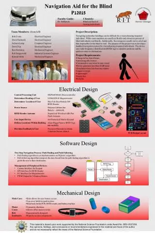
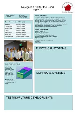
Design Goals • Able to communicate effectively with deaf blind individuals • Weight cannot exceed 4 ounces • Must fit within a 4 x 2 x 1 inch volume • Must be reasonably inconspicuous • Will track position using RFID tags • Power must last for ten twenty minute uses • Cost to produce must not exceed $700 *antenna not counted in weight and size requirements
Concerns • Volume Constraints • Weight Constraints • Heat Dissipation • Attaching device to belt • Program Accuracy • PCB Design and Functionality
Power Consumption Battery is 3.7V, 1100mA*hr, 4.01W*hr
Heat Analysis – Hand Calculations • Conduction caused by air: • Section of chip 0.1” x 0.1” • A=6.45*10-6 m2 • Q= -KA (dT/dx) • QTotal=1.6W • QPart =1.6W/210 = 0.00762W • K= (about) 0.0257 Wm-1K-1 • dT/dx = Q/(-KA) • dT/dx = 0.00762/(0.0257*6.45*10-6) = 45969 degC/m =649 degF/in =64.9 degF/0.1in Air Chip
Heat – Experimental Results Null hypothesis: Average temperature < 120 deg F 95% Confidence Alpha = 0.05 Mean=113.9 P-Value=1.00 Fail to reject null hypothesis
Heat – Analytical Analysis Case thermal conductivity = 0.2 Wm-1K-1 Outside case temp set to 20 deg C Top of chip set to 54 deg Celsius (130 deg F) Bottom of chip insulated
Functional Decomposition 5) Receive Map Info 11) Compare current to map 18) Deliver Non-Prompted Information to User Via Haptic Feedback 20) Off Path 1) Region Map Connectivity of Modular Devices 21) Hardware Health 15) Monitor Hardware Health 12) Record location history Battery Life 6) ID current location 22) Movement Instructions 2) Nearest Tag ID(s) Turn 16) Calculate next movement instruction 13) Calculate path 19) Deliver Prompted Information to User Via Haptic Feedback Navigation Loop Destination Arrival 23) On Correct Path 7) Receive User Input 3) Destination 24) Button Pushed 17) Estimate Remaining Distance 25) Estimated Remaining Distance 4) User Input 8) Determine Orientation (Compass) (MCU: Define Interfaces with Power, User Input, Map Input, RFID Reader, Magnetometer, Output Drive Circuitry) 10) On-Board Power 14) Regulate Power 9) Charging Power Enclosure: Support & Manage Internal Components
Final Design • Design elements kept from previous years • RFID tag and reader • Keypad input • Changes from previous years • Vibratory haptic feedback • Two motors for directional feedback • One motor in base unit for input confirmation • Modular belt design • Two motors • Base unit with keypad • Separate antenna
Procedure of Build • Week 1 • Motor Testing (without case) • Antenna Testing • PCB Prototyping Board • Week 2 • Finalize design and build motor case • Motor Tests (with case) • Testing of Magnetometer • Order Wiring and Belt • Week 3 • Order Base Case • Test Keypad
Procedure of Build Cont’ • Week 4 • Test PCB • Start design for part placement in case • Order spacers and insulation for case • Have developed program to start testing • Week 5 • Re-machine Case and continue fitting parts • Test connections and interactions between MCU and other devices • Order PCB • Week 6 • Test Durability of general design • Finish Full Build • Week 7 • Application testing of device • Week 8 – 10 • Presentation Set up
Haptic Feedback Motors Navigation Feedback Input Confirmation Pico Vibe 12mm Vibration Motor - 3.4mm Type • Precision Haptic 10mm Vibration Motor - 15mm Type
Motor Tests • Volt Step Testing • Orientation Testing • Case Material Testing • Duty Cycle Testing • Applied Force on Case
Testing of Total Design • Heat • Internal Temperature must be less than 120 degrees Fahrenheit • Drop • Must be fully functional after a free fall drop from 3 feet • Guidance • Must accurately guide an individual from any location on the second floor of Building 9, to any designated location
Testing of Total Design (cont’) • Battery Replacement • Must take less than 1 minute • Charge Time • Charges in 8 hours or less • Power Consumption • Can Run for at least 200 minutes on 1 charge • Removal and attachment of device • Less than 1 minute
Risk Assessment • MCU Lead Time Taking too long • Motors Vibrating too had for leads • Motors Burning Out • Fails Drop Test • Keypad Lead Time
? Questions