Turbocharger
Turbocharger. Made by. Yu-Ching Hu. Ship’s General Arrangement Plan. Turbocharger. Main propulsion for MT “Bunga Kasturi Empat” Gross : 156,967 Tonnages Maker : Hitachi Zosen B&W 7S80MC (MK 6) with 22580kw/75.9rpm Year of build: 2007. Definition:.


Turbocharger
E N D
Presentation Transcript
Turbocharger Made by Yu-Ching Hu
Turbocharger Main propulsion for MT “Bunga Kasturi Empat” Gross : 156,967 Tonnages Maker : Hitachi Zosen B&W 7S80MC (MK 6) with 22580kw/75.9rpm Year of build: 2007
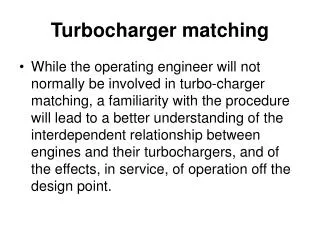
Definition: It should be emphasized that a turbocharger does not basically change the operating characteristics of an engine. A turbocharger is not a power source within itself. The turbocharger's only function is to supply a greater volume of compressed air to the engine so that more fuel can be burned to produce more power. It can function only as dictated by the flow, pressure and temperaturein the engine exhaust gas. 定義: 為什麼要使用渦輪增壓呢?以目前四行程引擎來說,它只能發揮汽油中大 約30%的更量,其餘的能量都浪費掉了(多數化成熱能)。在這種情況下,如果要獲得更多的動力,只好燃燒得多的燃料了,但只是增加燃料是不行的,因為燃燒需要空氣,所以重點如何讓引擎吸入更多空氣。由於自然吸氣引擎靠大氣壓力把空氣壓入氣缸,氣缸內的氣壓大概也只能有一個大氣壓力 ,於是引擎吸入的空氣量受到氣缸容積所限,為了讓同容積的氣缸吸入更多空氣,只好強制把空氣把空氣壓入氣缸,這樣一來氣缸就能吸入較多的空氣了。而渦輪增壓器的功能就是把更多的空氣壓入氣缸。
渦輪增壓的原理 渦輪增壓原理就是利用引擎運轉時所排出來的廢氣來推動渦輪增壓器中的排氣側轉子(Turbine)的驅動葉片,而排氣側轉子與進氣側轉子(Compressor)是同在一根軸上的,當排氣氣側轉子達到一定轉速時(約12000rpm左右),它會帶動另一側的進氣側轉子,使進氣側轉子引進外來的新鮮空氣,經過壓 倒入進氣歧管內。所以渦淪增壓的進氣是非自然方式,而經過”吸進來,再壓縮”,所以空氣壓力 大於大氣壓力的。這也就是渦輪增壓引擎(turbo)和自然吸氣引擎(NA)最大的不同點了。
渦輪增壓機的特性: 1. 增壓機是目前船上最具經濟效率的機器,重量僅為引擊全部重量之2~3% ,但引擎馬 力之輸出則增加50~100%。 2. 對同型引擎而言因裝置過給機,其最高壓力,平圴温度,平均有效壓力均升高最大 可達 20kg/cm2。 3. 引擎單位馬力重量可減輕30~40%,同時單位馬力的面積和容積也得以減少。 4. 同一出力之引擎,有過給機者氣缸數可減少,所以機艙容積可有效利用。 6. 機械經過過給以後,燃燒情況改良,機械效率增加,燃料消費率也隨著降低3~5%。 7. 任何一種過給機皆具有掃排氣孔的共同缺點,吸入或止回閥均甚易污穢或失效。當空氣排出受到阻流情況,在高負荷下時,將產生過荷,終使引擎性能低落。因此平 日清潔保養工作便更形重要。 History The turbocharger was invented by Swiss engineer Alfred Büchi. His patent for a turbocharger was applied for use in 1905.[1]Diesel ships and locomotives with turbochargers began appearing in the 1920s.
一般而言,中型渦輪機可達到每秒400rpm的轉速,葉片末端更可高達音速的1.5倍。(音速相當於每秒340.29公尺,時速約1224公里)。一般而言,中型渦輪機可達到每秒400rpm的轉速,葉片末端更可高達音速的1.5倍。(音速相當於每秒340.29公尺,時速約1224公里)。 再者渦輪機必須接受內燃機所排放出的燃燒高溫廢氣,進而作動排氣側轉子;而所有的動作皆可能在高達攝氐700度高溫下進行。故所有渦輪機的配件都必須是更精密的機件所組成。 根據統計:最近幾年內燃渦輪機損壞的192案件中,請求保險理賠的金額 約美金2500萬元,而所衍生出其他的費用更是無法估計 ,由此更可見渦輪機平常維修保養的重要性。
渦輪增壓機故障的原因: • 延遲保養或維修的時間: • Due to operational and economic constraints, overhauls are sometimes postponed until dry-docking rather than overhauling while the ship is in service. 2. 使用替代品: To reduce the costs of maintenance and parts, owners will use “pirate” or “alternative source" parts in place of manufacturer's parts. Due to the rough service environment of a turbocharger, inferior quality parts with slight discrepancies in material, design and dimensions can easily lead to damage. • 3. 不適當的維修與保養: • Failure to observe the right fitting sequence may pre-damage components.- Failure to exchange key wear parts may lead to loss of functionality, for instance to loss of • bearing lubrication.- Failure to observe the correct clearances of the assembly and to adjust the right true run of • rotors may lead to rubbing of the rotor with consequential imbalance. - Improper cleaning of cover rings can lead to blade rubbing and consequent blade failure • when installing overhauled rotors.
4. 遺失維修保養記錄: When there is a change of ownership of a vessel, the service letters and logbooks for the turbocharger (as well as other critical pieces of machinery and equipment) can be missing. This break in information does not allow the new owners or ship managers the opportunity to assess the maintenance and services needs of the turbochargers. 5.不適當的操作: Depending upon the ship's trade and operation, engines and turbochargers are sometimes specified for "slow steaming". When greater load demands are again made on such equipment, some components may need to be replaced to match the new operating conditions. If disregarded, the result may be operational problems and/or reduced life cycle of the rotating parts of the turbocharger due to elevated speed. 6. 維修過程中的疏忽: In many cases, damage to turbochargers may occur when maintenance has been conducted on other machinery components or systems upstream of the turbocharger. Since the turbocharger is downstream of most other engine machinery, any foreign objects, loose parts, forgotten equipment or pieces of machinery equipment that may have not been properly reassembled may eventually move downstream to damage the turbocharger.
Recommendations - Only qualified manufacturer-approved maintenance personnel should perform maintenance to turbochargers. In most cases, the most qualified to perform maintenance and overhauls are the manufacturers themselves, where repairs can be performed while the ship is in service or at dry-dock. Some companies and shipyards are willing to perform turbocharger maintenance and overhaul at a "cheaper" cost than the manufacturer. Although these reduced costs may be attractive to shipowners and ship managers, they may represent a false economy if damage occurs due to inadequate maintenance - this can, in the end, be very costly to the owner and/or underwriter. When qualified personnel perform the work, workmanship is normally under warranty. - Use the correct manufacturer's replacement parts. The turbocharger is a highly loaded, high technology engine component. Therefore, it is imperative to maintain and overhaul it with the correct parts. As with the maintenance work, the parts will also normally be under warranty. - Ensure that proper records are obtained and turbocharger service documents and letters kept. This is to ensure that proper maintenance and service can be scheduled. In cases where the service documents and letters are not available upon sale of the ship, the equipment manufacturer can often help with proper documentation and sometimes even with the turbocharger service history.
- Operate the turbocharger within the operational design parameters. Damage incurred due to improper use can be very costly by leading to operation at reduced speed, or a total breakdown of the turbocharger, loss of hire due to the need for maintenance and repair. Therefore, important parameters such as turbocharger speed and exhaust gas temperatures should be routinely monitored and if possible used as input to trigger alarms. - Ensure proper care and maintenance of the turbocharger. Turbocharger care and maintenance are required at regular intervals and should be in accordance with the manufacturer's recommendations. If in doubt, contact the equipment manufacturer for information on component service life. Proper care and maintenance include: - Water cleaning of compressors and turbines to remove dirt and other residual material from the rotor to ensure proper balance.- Regular cleaning and changing of air intake filters to prevent foreign objects entering and dirt and residue build-up on the rotor blades. Furthermore, contamination of air intake filters results in a higher inlet restriction and may cause turbocharger overspeed or surging.- In case of turbocharger separate lubricating system: regular changing of lubricating oil (consult manual for approved oil) and cleaning of centrifuges as well as filters.
CRANKCASE EXPLOSION CASUALTY INVESTIGATION BRITISH VALOUR - OFFSHORE BERMUDA 23.03hrs (GMT) 18 MARCH 2001
1.0 NARRATIVE Whilst en route between her loading port of Sture (Norway) and her discharge port of Freeport (Texas) and when the vessel was some 80 nautical miles South East of Bermuda, the Isle of Man registered ship British Valour suffered a crankcase explosion creating an oil mist external to the main engine, which ignited. The vessel has a length of 343.71m overall, beam of 56.40m and depth of 30.40m, accommodation is situated aft, above and around the engineroom casing. Decks are identified by their distance above the baseline in the engineroom and by letter in the accommodation, ascending from the main deck and finishing with the navigating bridge. The main engine is a B&W 8 UEC 75 LLII built under licence by Mitsubishi Heavy Industries in Japan, it has a bore of 750mm, stroke of 2800mm and develops 23,535 kW at 84rpm. The vessel was full away on passage carrying a cargo (272,386 tonnes) of Oseberg crude oil. Normal navigational watches were being maintained and the engineroom was operating in an unmanned condition. Just after 18.00hrs local time, two detonations were heard in the engineroom followed by activation of the general alarm, numerous zones of the engineroom fire detection system were in an alarm condition, the system then failed.
2.0 INVESTIGATION FINDINGS: 2.1 The engineroom was smoke/soot blackened on the starboard side, deck plates around the cylinder head area were distorted and dislodged from their original location, thermoplastic diffusers on fluorescent light fittings had melted sufficiently to flow easily under gravity and their own weight, physical contact damage was apparent in a number of locations. Bulkhead above turbocharger Bottom plates starboard side Shadow area in way of deep frame
2.2 External signs were that all eight crankcase explosion relief valves (located on the starboard side of the engine) had lifted, nos. 2, 5 and 6 were found to have incorrectly seated after closing under pressure from their return springs. Additionally two of the sealing rubber ‘o’ rings had become dislodged from their seats. Crankcase relief valves 2 & 3, Sooty above, clear below Relief valve No.4 following dismantling Deck plating by turbochargers Damaged florescent light fittings
3.0 ANALYSIS AND COMMENTS 3.1 The failure of no.1 unit, piston crown, allowed direct communication of the combustion chamber with the crankcase via the piston cooling oil passages. This allowed hot combustion gases to create and ignite a flammable oily mist mixture from the oil droplets normally present in the crankcase, causing a primary crankcase explosion. 3.2 The crankcase explosion relief valves operated to relieve the pressure inside the crankcase but failed to re-seat properly, thus allowing air back inside the engine to give conditions suitable for a second explosion to take place, the source would give the possibility for ignition at every firing cycle until fuel was removed from the injection system. 4.0 RECOMMENDATIONS 4.1 Modifications to the relief valve and flame arresting arrangements fitted, have been made by the licensed engine makers for new engines of this type since the incident. 4.2 The licensed engine makers, student at University College London - conducted research into the prevention and containment of crankcase explosions in conjunction with Lloyds Register have brought about a design change both to the relief valve itself and the flame arrestor for this type of engine as a direct result of this casualty, they have circulated information in respect of this and they recommend that in the interests of safety, the modifications be undertaken. Whilst costs for this work will be included in new engine pricing, existing modifications would have to be carried out at a cost to the owners.
As the sources of explosion vary to a large extent, this must be taken into consideration when taking precautions and selecting monitoring systems. Below is a table of a number of accidents where the cause of explosion is known, the table includes two-stroke engines of both our design and of our competitors’ designs: Table I: Cases of explosions where the cause is known Year Cause of Explosion Cause of Failure 1995 Bearing in PTO gearbox 1996 Inlet pipe for piston cooling oil falling off Incorrect tightening 1997 Incorrect spring mounted in piston rod stuffing box Unauthorised spare part 1997 Piston rod interference with cylinder frame 1999 Weight on chain tightener falling off Incorrect tightening 1999 Fire outside the engine 2000 Main bearing 2000 Camshaft bearing 2000 Incorrect shaft in camshaft drive Unauthorised spare part 2001 Crankshaft failure 2001 Piston crown failure 2001 Main bearing 2001 Crankpin bearing 2002 Inlet pipe for piston cooling oil falling off Incorrect tightening
ACKNOWLEDGEMENTS The author would like to thank : • MAN B&W diesel AS for making available research presentation material into the design and effectiveness of crankcase relief valves and flame arresting systems. • BP Shipping Limited for readily supplying historical records and information that they discovered in respect of this incident. • http://tw.wrs.yahoo.com/_ylt=A3eg8_gmmRhLW1EBc_l21gt./SIG=126qq6m0o/EXP=1259989670/**http%3A//www.flickr.com/photos/costisnet/2702397868/ • http://www.flickr.com/photos/costisnet/2702397868/ • Gard News 162 May/July 2001 • Gard News 159 September/November 2000 • http://www.brighthub.com/engineering/marine/articles/29555.aspx#ixzz0YPCnigQP • 船舶輪機實務----------樓無畏
Question • 1.渦輪增壓機故障原因,可概分為六類。試依ITC 1/10/83 Clause 6 Perils,哪些類別可獲理賠?依據何條款?試解釋之。 • 2.試詳解ITC 1/10/83 Clause 6.2.2 bursting of boilers breakage of shafts or any latent defect in the machinery or hull的其中latent defect並詳解保險人賠償範圍。