NETWORK TOPOLOGIES
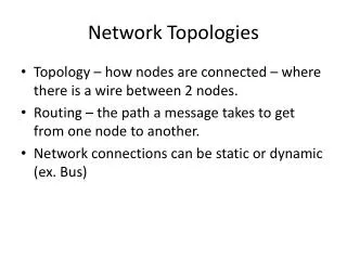
NETWORK TOPOLOGIES. There are three basic configurations used to connect computers they are the Bus Ring Star. Bus topology. This type of network was widely used in the 1980’s In this configuration every computer (node) shares the networks total bus capacities.

NETWORK TOPOLOGIES
E N D
Presentation Transcript
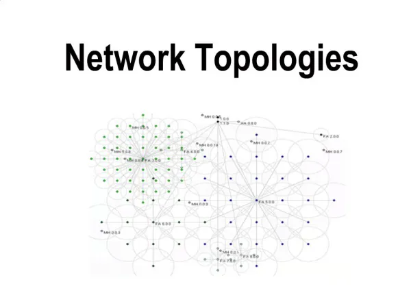
NETWORK TOPOLOGIES There are three basic configurations used to connect computers they are the Bus Ring Star
Bus topology • This type of network was widely used in the 1980’s • In this configuration every computer (node) shares the networks total bus capacities. • In this configuration adding more computers will reduce the access speed on the network. • Each computer communicates to other computers on the network independently this is referred to as PEER-TO-PEER networking
How a Bus Peer to Peer Network Works • All computers on a network have a distinct address just like your house does • a message would be send from one computer with the address of another computer attached to the message • The message is broadcasted to all the computers on the network until the addressed PC accepts the message
How it worked • The type of wires used for Bus Networks in the 80’s were called Thicknet and Thinnet • A Thicknet cable (very large about 1 inch in diameter usually yellow was hung around a room) • Thinnet cables were connected to the PC’s NIC and a Transceiver. The Transceiver was tapped into the Thicknet cable • To stop the message from bouncing back and forward down the wire (known as signal bounce) both ends of the network are terminated with 50Ω resistors
Problems • One of the main problems with this type of network is that it is not very fault tolerant, a break or defect in the bus would affect the whole network
Ring Topology • In Ring topology each node is connected to the two nearest nodes so the entire network forms a circle • Data only travels in one direction on a Ring network
How this Topology works • a node has information to send to another computer on the network so it sends the information out on the network to the PC it is connected to, if the information is for this PC (the recipients NIC address is attached to the message, which is like putting an address on an envelope) then the PC accepts the data • otherwise it passes the information on to the next PC by repeating the data back out on the line • This method of repeating the data helps keep the integrity of the data readable by other computers
How it Works • As it is better to have computers take turns using the connecting Data cable, Ring topologies incorporated a system called Token passing • In this topology, to transmit on the wire your computer must have control of the token or wait for the token to be free • Larger Token Ring networks use multiple tokens
Problems and Solutions • The drawback to this type of topology is that a single malfunctioning workstation can disable the whole network • To make sure all the information is sent the receiving PC sends the token back to the sending PC after it has received all the data • If the sending PC is finished sending it passes the token to the next PC • This type of network was also widely used in the 1980’s • This type of network used Thinnet cable joining nodes. • In the mid 1980’s Thinnet cable was replaced by Category 3 Ethernet cable capable of handling up to 10Mbps
HUB Star topology • In a Star topology every node is connected through a central device such as a Hub, Switch or Router • Compared to a Ring or Bus topology a Star topology requires that more thought be put into its setup
The Good and Bad of a Star Network • The upside of a star network is that if any one cable fails then only the node connected on that cable would be affected • Another positive point to this type of network is that it is very simple to join two star networks together by connecting their central devices to each other
The Good and Bad of a Star Network • As each computer is connected to a central device (Hub) the location of the Hub must be made as central as possible, so as to reduce cable lengths • The drawback to this type of topology is if a central device was to fail then all computers connected to that device would not be able to see the network
What is a Hub? • A hub is usually a small rectangular box, often made of plastic, which receives its power from an ordinary wall outlet • A hub joins multiple computers (or other network devices) together to form a single network segment • On this network segment, all computers can communicate directly with each other
What is a Hub? • Ethernet hubs are by far the most common type, but hubs for other types of networks such as USB also exist • A hub includes a series of ports that each accepts a network cable • Small hubs can network four computers together • They contain four or sometimes five ports
What is a Hub? • Many times the fifth port is reserved for "uplink" which is the connecting of one hub to another hub or similar device (joining two segments together). • Larger hubs contain eight, 12, 16, and even 24 ports
Key Features of Hubs • Hubs classify as Layer 1 devices in the OSI model • OSI stands for : The Open Systems Interconnection Basic Reference Model • At the physical layer, hubs can support little in the way of sophisticated networking • Hubs do not read any of the data passing through them and are not aware of their source or destination
Key Features of Hubs • Essentially, a hub simply receives incoming packets, possibly amplifies the electrical signal, and broadcasts these packets out to all devices on the network - including the one that originally sent the packet! • a packet is a formatted block of data carried by a computer network
Different Types of Hubs • Technically speaking, three different types of hubs exist Passive Active Intelligent
Passive hubs • Passive hubs do not amplify the electrical signal of incoming packets before broadcasting them out to the network Active hubs • amplify the electrical signal of incoming packets back to their original level before broadcasting them back out on the network
Intelligent hubs • add extra features to an active hub that are of particular importance to businesses • An intelligent hub is typically stackable (built in such a way that multiple units can be placed one on top of the other to conserve space).
Intelligent hubs • It also typically includes remote management capabilities via SNMP and virtual LAN (VLAN) support (You can configure or check it from a computer that is connected to it). • SNMP-Simple Network Management Protocol
What is a Network Switch? • A network switch is a small hardware device that joins multiple computers together within one local area network (LAN) • Technically, network switches operate at layer two (Data Link Layer) of the OSI model
Network Switch • Network switches appear nearly identical to network hubs, but a switch generally contains more "intelligence" (and a slightly higher price tag) than a hub • Unlike hubs, network switches are capable of inspecting data packets as they are received, determining the source and destination device of that packet, and forwarding it appropriately
Network Switch • By delivering each message only to the connected device it was intended for, a network switch conserves network bandwidth and offers generally better performance than a hub
What is a Router? • Routers are physical devices that join multiple wired or wireless networks together • Technically, a wired or wireless router is a Layer 3 gateway, meaning that the wired/wireless router connects networks together • A Gateway is a device that acts like a security guard and only allows data in or out if it has the right network headers
Routers • Home “networkers” often use an Internet Protocol (IP) wired or wireless router • IP is the most common OSI network layer protocol • Protocols are the rules governing the transfer of data information, it can also be compared to how humans use languages (to get your point across you must talk in the same language as the person you are speaking to).
Routers • An IP router such as a DSL or cable modem are broadband routers and joins the home's local area network (LAN) to the wide-area network (WAN) of the Internet • A Broadband Router is a device that allows multiple PC’s to access the Internet using only one address.