Chapter 4 Circuit-Switching Networks
Chapter 4 Circuit-Switching Networks. 4.1 Multiplexing 4.2 SONET Transport Networks Circuit Switches The Telephone Network Signaling Traffic and Overload Control in Telephone Networks Cellular Telephone Networks. Circuit Switching Networks.

Chapter 4 Circuit-Switching Networks
E N D
Presentation Transcript
Chapter 4 Circuit-Switching Networks 4.1 Multiplexing 4.2 SONET Transport Networks Circuit Switches The Telephone Network Signaling Traffic and Overload Control in Telephone Networks Cellular Telephone Networks
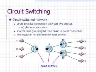
Circuit Switching Networks • End-to-end dedicated circuits between clients • Client can be a person or equipment (router or switch) • Circuit can take different forms • Dedicated path for the transfer of electrical current • Dedicated time slots for transfer of voice samples • Dedicated frames for transfer of Nx51.84 Mbps signals • Dedicated wavelengths for transfer of optical signals • Circuit switching networks require: • Multiplexing & switching of circuits • Signaling & control for establishing circuits • These are the subjects covered in this chapter
How a network grows • A switch provides the network to a cluster of users, e.g., a telephone switch connects a local community Network Access network (b) A multiplexer connects two access networks, e.g., a high speed line connects two switches
a b A d c Network of Access Subnetworks A Network Keeps Growing 1* b a 2 4 (a) Metropolitan network A viewed as Network A of Access Subnetworks 3 A c d Metropolitan (b) National network viewed as Network of Regional Subnetworks (including A) A • Very high-speed lines Network of Regional Subnetworks National & International
Chapter 4Circuit-Switching Networks 4.1 Multiplexing
(a) (b) A A A A B B MUX MUX B B C C C C Multiplexing • Multiplexing involves the sharing of a transmission channel (resource) by several connections or information flows • Channel = 1 wire, 1 optical fiber, or 1 frequency band • Significant economies of scale can be achieved by combining many signals into one • Fewer wires/pole; a fiber replaces thousands of cables • Implicit or explicit information is required to demultiplex the information flows. Shared Channel
A channel divided into frequency slots Guard bands required AM or FM radio stations TV stations in air or cable Analog telephone systems B f A f 0 Wu C C 0 Wu f 0 Wu B A f W 0 Frequency-Division Multiplexing (a) Individual signals occupy Wu Hz (b) Combined signal fits into channel bandwidth
A1 A2 … t 0T 6T 3T B1 B2 … t 6T 3T 0T C1 C2 … t 0T 6T 3T C2 A2 B2 … A1 C1 B1 t 0T 1T 2T 3T 4T 5T 6T Time-Division Multiplexing (a) Each signal transmits 1 unit every 3T seconds • High-speed digital channel divided into time slots • Framing required • Telephone digital transmission • Digital transmission in backbone network (b) Combined signal transmits 1 unit every T seconds
1 1 2 MUX 2 MUX . . . . . . 22 23 24 b 24 2 1 b . . . Frame 24 24 T-Carrier System • Digital telephone system uses TDM. • PCM voice channel is basic unit for TDM • 1 channel = 8 bits/sample x 8000 samples/sec. = 64 kbps • T-1 carrier carries Digital Signal 1 (DS-1) that combines 24 voice channels into a digital stream: Framing bit • Bit Rate = 8000 frames/sec. x (1 + 8 x 24) bits/frame • = 1.544 Mbps
1 DS1 signal, 1.544Mbps . . Mux 24 1 DS2 signal, 6.312Mbps . 24 DS0 . 4 DS1 Mux 4 1 DS3 signal, 44.736Mpbs . . 7 DS2 Mux 7 1 . . 6 DS3 Mux 6 DS4 signal 274.176Mbps North American Digital Multiplexing Hierarchy • DS0, 64 Kbps channel • DS1, 1.544 Mbps channel • DS2, 6.312 Mbps channel • DS3, 44.736 Mbps channel • DS4, 274.176 Mbps channel
1 2.048 Mbps . . Mux 30 1 8.448 Mbps . 64 Kbps . Mux 4 1 34.368 Mpbs . . Mux 139.264 Mbps 1 . . Mux 4 CCITT Digital Hierarchy • CCITT digital hierarchy based on 30 PCM channels • E1, 2.048 Mbps channel • E2, 8.448 Mbps channel • E3, 34.368 Mbps channel • E4, 139.264 Mbps channel
MUX t 2 5 4 3 2 1 5 4 3 1 Clock Synch & Bit Slips • Digital streams cannot be kept perfectly synchronized • Bit slips can occur in multiplexers Slow clock results in late bit arrival and bit slip
Muxing of equal-rate signals Pulse stuffing Pulse Stuffing • Pulse Stuffing: synchronization to avoid data loss due to bit slips • Output rate > R1+R2 • i.e. DS2, 6.312Mbps=4x1.544Mbps + 136 Kbps • Pulse stuffing format • Fixed-length master frames with each channel allowed to stuff or not to stuff a single bit in the master frame. • Redundant stuffing specifications • signaling or specification bits (other than data bits) are distributed across a master frame. requires perfect synch
Optical fiber link carries several wavelengths From few (4-8) to many (64-160) wavelengths per fiber Imagine prism combining different colors into single beam Each wavelength carries a high-speed stream Each wavelength can carry different format signal e.g., 1 Gbps, 2.5 Gbps, or 10 Gbps Optical deMUX Optical MUX 1 1 2 1 2 2. m Optical fiber m m Wavelength-Division Multiplexing
Example: WDM with 16 wavelengths 30 dB 1540 nm 1550 nm 1560 nm
Chapter 4Circuit-Switching Networks 4.2 SONET
SONET: Overview • SynchronousOptical NETwork • North American TDM physical layer standard for optical fiber communications • 8000 frames/sec. (Tframe = 125 sec) • compatible with North American digital hierarchy • SDH (Synchronous Digital Hierarchy) elsewhere • Needs to carry E1 and E3 signals • Compatible with SONET at higher speeds • Greatly simplifies multiplexing in network backbone • OA&M support to facilitate network management • Protection & restoration
MUX MUX DEMUX DEMUX Insert tributary Remove tributary MUX DEMUX ADM Insert tributary Remove tributary SONET simplifies multiplexing Pre-SONET multiplexing: Pulse stuffing required demultiplexing all channels SONET Add-Drop Multiplexing: Allows taking individual channels in and out without full demultiplexing
SONET Specifications • Defines electrical & optical signal interfaces • Electrical • Multiplexing, Regeneration performed in electrical domain • STS – Synchronous Transport Signals defined • Very short range (e.g., within a switch) • Optical • Transmission carried out in optical domain • Optical transmitter & receiver • OC – Optical Carrier
DS1 Low-speed mapping function DS2 STS-1 E1 51.84 Mbps Medium speed mapping function DS3 STS-1 44.736 OC-n STS-n STS-1 STS-1 High- speed mapping function E4 STS-1 STS-1 Scrambler E/O STS-1 STS-1 139.264 . . . . . . STS-3c MUX STS-3c High- speed mapping function ATM or POS SONET Multiplexing