CMS Tracker
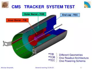
CMS Tracker. CMS Tracking Workshop Fermilab 8/3/04 R. Demina University of Rochester. Outline. Overview Production model and parts flow Sensors Hybrids Alignment Test beam Summary. Bat 40. Civil Engineering and Magnet. TOB. TOB. TEC. TEC. TIB. TIB. TID. TID. PD. PD.

CMS Tracker
E N D
Presentation Transcript
CMS Tracker CMS Tracking Workshop Fermilab 8/3/04 R. Demina University of Rochester
Outline • Overview • Production model and parts flow • Sensors • Hybrids • Alignment • Test beam • Summary
TOB TOB TEC TEC TIB TIB TID TID PD PD Inner Tracker 2-3 pixels + 10-14 strip hits
Modules CF frames assembled in Pakistan 500 mm Sensors from ST MicroElectronics Full flex kapton circuit from Cicorel ~20 cm ~5,600 Tracker Outer Barrel (TOB) modules constructed at FNAL & UCSB FNAL and UCSB will have equal capabilities and capacity
CMS Tracker Organization UCSB FNAL Sensors: Pitch adapter: Frames: Hybrid: Hybrids: US CMS in the overall tracker organization factories Brussels Brussels CF carrier Strasbourg CERN UR Pisa Perugia Wien Louvain Sensor QAC Karlsruhe Strasbourg Module assembly Perugia Bari Lyon UCSB Brussels Wien FNAL Bonding & testing Wien Zurich Strasbourg Karlsruhe Aachen Padova Pisa Torino Bari Firenze Integration into mechanics ROD INTEGRATION TIB - TID INTEGRATION PETALS INTEGRATION Aachen Louvain Lyon Strasbourg Karlsruhe Pisa FNAL Brussels UCSB TOB assembly TIB - ID assembly TEC assembly TEC assembly Sub-assemblies CERN Pisa Aachen Karlsruhe . -- > Lyon TK ASSEMBLY CERN
Overview TOB Module Summary Table • FNAL and UCSB will have equal capabilities and capacities • FNAL production line • Gantry operational – made ~20 operational TOB modules. • 2 of 4 DAQ and 2 of 4 ARCS • UCSB Production line • Gantry operational –made 4 operational TOB modules • 1 of 3 DAQ and 2 of 5 ARCS • UCR module diagnostics and repair • 0 of 1 DAQ and 0 of 1 ARC
Module Construction -Pipeline 3519: hybrids delivered 1939: modules assembled 1646: modules delivered to bonding centers 1489: bonded 1423: Tested with ARC 1344: are good (94%) TIB: 1055 Assembled 886 Tested 855 are good (96%) TOB: 294 Assembled 291 Tested 253 are good (87%) TEC: 590 Assembled 246 Tested 229 are good (93%) Thin sensors : TIB+TID 1055 of 3558 (30%) TEC 500 of 2512 (20%) Thick sensors : TOB 294 of 5208 TEC 90 of 3888
Silicon Sensors • Original plan: • Inner region TIB – thin (300um) sensors – HPK • Outer region TEC, TOB– thick (500um) sensors – ST Microelectronics • Inner region – consistently high quality, occasional drift of resistivity (resolved) • Outer region – x7 higher current, vacuum, stress, humidity dependency, higher number of bad channels, some channels go into early breakdown and saturate APV (Microdischarge) • July 2004 – decision to cancel the production order with ST (after a year of deliberations)
Hybrid Production Overview Need ~ 17000 1450/month ( 8.5% /month) 35% • This plot still includes the rejected batches • The gap between ‘bonded’ and ‘shipped’ are the hybrids bonded in the US • The gap between ‘shipped’ and ‘assembled’ are the hybrids in the processing pipeline and the assembled hybrids from rejected batches that were not shipped. Bonded : 700/month
New hybrid problem On April 19th it was reported that two TOB modules had an anomalous behavior of the pedestals after several ( 10-20 ) minutes of tests. It was quickly traced back to an open in the via to a calibration pad of the APV. This open escapes the FIT test ( < 1 min) but should not escape the QC at Cicorel. The via opened AFTER the hybrid left Cicorel. The Via affected is a long via: i.e. from layer 1 to layer 4 A new test was designed to identify this fault in a short ( 10”) amount of time and many hybrids were tested with this method. We had a number of cases with multiple faults in the same hybrid Cicorel was alerted and cuts have been made on bad hybrids
A “so called” good via CK K CS G Ni The new Hybrid Problem A NORMAL AND “GOOD” VIA The circuit is made with 2 plates of kapton (K) with 18 microns layers of copper on each side (CK). These 2 plates are glued together (G). The via is drilled using a laser beam, which is focused and defocused when it goes through the kapton, copper or glue. And after this drilling about 15 microns of copper is deposited (CS), and a thin layer of Nickel (Ni) – see the different color – is also chemically deposited. What is observed is an “overetching” of the glue layer due to a different behaviour under the laser beam and (to a lesser extend) at the plasma cleaning stage.
On this via,the overetching is so large than the copper is almost absent.Picture taken from one hybrid send back to CICOREL (probably from CERN last week, maybe from Strasbourg) Bottom layer Isotac Ceramic A bad via
Actions • Cicorel restarts the production with new settings. The new hybrids should be delivered to CERN ~ middle of July. • Implement more strict quality control at Cicorel during hybrid production • Evaluate the quality of the existing batches on batch to batch bases. This is a difficult task since we have no full information • Perform aging tests with thermal cycles on existing batches to assess the long term reliability of the delivered hybrids • Preliminary results show that the failure rate on the hybrids of the bad TOB batch is larger ( ~ 10) than on the other batches.
FNAL Gantry Random Errors Mod 1 Mod 2 Original 5 mm spec not always met. 10 mm is ok May be improved… Without 2D With 2D Mod 3
Test beam X5 TOB set up with 6 (2DS, 3 SS4, 1 SS6)rods mounted in a TOB-Like Structure 1 full control ring – Read out with Final FED and FEC .
Test beam at X5 • FED9U works Zero suppression works • Internal pedestal + common mode noise subtraction • Zero suppression being studied – first results encouraging S/N=36 Read 512 strips/module Clusters done offline Cluster are done in the FED and read only clusters
Summary • CMS tracker- all silicon system : 2-3 pixels + 10-14 strip hits • Production distributed over Europe and US • Silicon sensors – July 2004 - place full production order with HPK • Still working out the legalities with ST • Potentially dangerous problem with Hybrids – “bubble” via • Working with company to improve QA • Gantry alignment <10 um • Test beam performance S/N=36 • 2004-2005 – critical year