Download
1 / 19
190 likes | 318 Vues
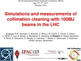
Simulations and measurements of LHC loss maps in physics R . Bruce, E. Skordis Collimation team, FLUKA team. Outline. Introduction and motivation: LHC cleaning requirements The SixTrack program Simulated machine scenario and simulation setup

E N D
Simulations and measurements of • LHC loss maps in physics • R. Bruce, E. Skordis • Collimation team, FLUKA team
Outline • Introduction and motivation: • LHC cleaning requirements • The SixTrack program • Simulated machine scenario and simulation setup • Comparison between SixTrack simulations and measurements • Loss locations around the ring • Ratio of losses at selected locations • FLUKA simulations of BLM response • Factors influencing the BLM response • Simulation results for BLM response at TCT and TCP • Comparison with measured loss maps at TCTs including BLM response RB ES
LHC cleaning requirements • Very high stored energy in LHC (nominal 362 MJ). Maximum specified loss rate from beam = 500 kW • LHC has superconducting magnets: design quench limit is 8.5 W/m. We need a very efficient collimation system! • We need a very good understanding of the beam cleaning and the ability quantitatively predict losses around ring • SixTrack with collimation routine used in the past during the design stage. Still used for performance estimates of collimation in the present and future LHC. • We have a strong interest to verify the predictive power of SixTrack! Preliminary comparisons shown in CWG talks 25.10.10 and 19.12.2011 collimation Cold magnets 500 kW Beam loss < 8.5 W/m
SixTrack for collimation • Element-by-element thin-lens 6D magnetic tracking • Monte Carlo routine (K2) simulates scattering in collimators (multiple Coulomb scattering, ionization, single diffractive and point-like elastic and inelastic scattering) • Post-processing: compare with aperture modelto determine loss locations with 10cm precision • Starting conditions: ring shaped halo in transverse phase-space • All particles have high enough amplitudes to hit the primary collimator within one betatron oscillation. Not accounting for the diffusion populating halo – large gain in CPU time! • instead assumption on initial impact parameter: about 1 µm, but up to 50µm gives similar result (PhD C. Bracco) Impact parameter
Simulation setup • For detailed benchmark, studying the 2011 machine • Tracking 64e6 particles for 200 turns. • Separate simulations for horizontal and vertical betatron halo, B1 and B2.
Simulated losses around the ring: B1H • Main peak in IR7, with certain leakage to all other IRs • For comparison with measure-ments, losses binned in 1m intervals and normalized to highest loss at TCP
Measured loss maps • Loss maps taken regularly to qualify the cleaning • Signals recorded at BLMs around the ring during provoked losses • Cleaning inefficiency taken as ratio of BLM to highest BLM • Using data averaged over several 2011 loss maps. Variations seen! • Example: highest cold losses during 2010-2012 Courtesy B. Salvachua, Evian 2012 Considered loss maps
Loss maps: simulated and measured B1H Simulated perfect machine Qualitatively good agreement – main loss locations reproduced. Note log scale! Measured
Loss maps: B1H, zoom in IR7 Simulated Qualitatively good agreement – main cold loss locations reproduced. Additional BLM signals in IR7 on warm elements and collimators! Showers! Measured
Cleaning at selected locations, B1H • SixTrack results summed over 2m interval upstream of each BLM in the IR7 DS • For TCTs, dividing losses at TCP by losses at TCT • Measured: 2011 average, normalized to TCP Qualitative trends reproduced, but a few orders of magnitude of difference found. IR7 DS TCTs at high-luminosity experiments
Comparison of TCTs, all loss maps Simulated, Perf. machine • The TCT with max leakage in each loss map is in B2 the TCTV in IR1 for both H and V. Halo background higher in ATLAS than in CMS? • Again, qualitative agreement, but quantitative discrepancy • First step for improvement: include imperfections of collimation system as in C. Bracco PhD thesis: • R.m.serror on gap centre: 50 μm. • R.m.s error on gap size: 0.1σ. • R.m.s. error on jaw angle to beam: 200 μrad. • Jaw flatness errors: measured profile applied to all carbon collimators Measured
Loss map with collimator imperfections Simulated perfect machine With imperfections: losses outside IR7 increase Simulated, random imperf. 12
TCT losses including imperfections • With collimator imperfections, average over 25 seeds, the discrepancy with measured loss maps becomes smaller • Pattern in each loss map well reproduced, but lower magnitude Simulated, imperfections Measured
Observations • All limiting loss locations around the ring are well reproduced by SixTrack • Qualitatively good agreement in the loss distribution around the ring • When looking at individual loss locations, e.g. the TCTs, discrepancies of up to a few orders of magnitude are found • Need to keep in mind what we compare: simulated losses of beam protons on collimators or aperture vs measured BLM signal • When protons hit a collimator or the aperture, a shower is produced. Some created secondary particles make it outside the cryostat/tank to the BLMs where their energy deposition causes a signal • The BLM signal depends on the distance between the impact and the BLM, the materials, and the impact distribution • We cannot expect the BLM signal per lost proton to be the same everywhere!
Impact parameters on TCTs • To quantitatively estimate the BLM signals, we need to simulate the showering with FLUKA. Inelastic interactions on TCTs and TCPs forwarded to FLUKA team.
Impact parameters on TCP • Comparing transverse impacts on TCP and TCTs, horizontal halo B1 • TCTH IR1: average depth of inelastic interaction = 1.5 mm • TCP IR7: average depth of inelastic interaction = 0.04 mm • Clear that we expect a differencein terms of showering! • We expect a larger part of the shower to be developed within the tungsten jaws of the TCTs than in the TCP because of heavier material (W) with larger interaction cross sections and larger impact distribution • Higher BLM signal per lost proton in TCT than in TCP?
Evolution of stored beam intensity • Very high stored energy in LHC (nominal 362 MJ). Achieved stored energies lower, but we are also at half the energy and double the bunch spacing!