Download
1 / 17
170 likes | 290 Vues
This guide explains the core concepts of always blocks in Verilog, focusing on how these blocks trigger with specific input signals and manage assignments in digital circuit design. It differentiates between combinational and sequential logic, highlighting the importance of assignment completion within always blocks to prevent unintended latch behaviors. The text also provides examples of common constructs like AND gates, registers with synchronous and asynchronous resets, and the structural differences between Mealy and Moore machines. This knowledge is essential for effective digital design and simulation.

E N D
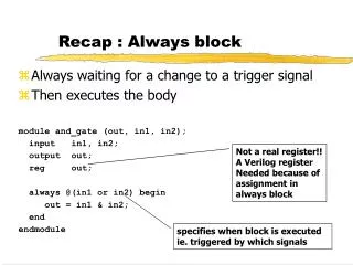
Recap : Always block • Always waiting for a change to a trigger signal • Then executes the body module and_gate (out, in1, in2); input in1, in2; output out; reg out; always @(in1 or in2) begin out = in1 & in2; end endmodule Not a real register!! A Verilog register Needed because of assignment in always block specifies when block is executed ie. triggered by which signals
Always block • A procedure that describes the function of a circuit • Can contain many statements including if, case • Statements in the always block are executed sequentially (except a case we will cover soon…) • The entire block is executed at once • The final result describes the function of the circuit for current set of inputs • intermediate assignments don’t matter, only the final result • begin/end used to group statements
“Complete” Assignments • If an always block executes, and a variable is not assigned • variable keeps its old value • NOT combinational logic latch is inserted • This is (most of the times) not what you want • Any variable assigned in an always block should be assigned for any execution of the block
Incomplete Triggers • Leaving out an input trigger usually results in a sequential circuit - again something we don’t usually want.. • Example: module and_gate (out, in1, in2); input in1, in2; output out; reg out; always @(in1) begin out = in1 & in2; end endmodule
Sequential Verilog • Sequential circuits are registers along with combinational logic • Register is synthesized when assignment is triggered by “posedge clk” module dreg (clk, d, q);input clk, d;output q;reg q; always@(posedge clk) q = d; endmodule
8-bit Register with Synchronous Reset module reg8 (reset, CLK, D, Q); input reset; input CLK; input [7:0] D; output [7:0] Q; reg [7:0] Q; always @(posedge CLK) if (reset) Q = 0; else Q = D; endmodule // reg8
N-bit Register with Asynch Reset module regN (reset, CLK, D, Q); input reset; input CLK; parameter N = 8; // Allow N to be changed input [N-1:0] D; output [N-1:0] Q; reg [N-1:0] Q; always @(posedge CLK or posedge reset) if (reset) Q = 0; else if (CLK == 1) Q = D; endmodule // regN
Blocking & Nonblocking Assignments • Blocking assignments (Q = A) • variable is assigned immediately before continuing to next statement • new variable value is used by subsequent statements • Non-blocking (delayed) assignments (Q <= A) • variable is assigned only after all statements already scheduled are executed • value to be assigned is computed here but saved for later • usual use: register assignment • registers simultaneously take their new values after the clock tick
Example always @(posedge CLK) begin temp = B; B = A; A = temp; end Swap : C style.. always @(posedge CLK) begin A <= B; B <= A; end But in hardware we can do things in parallel..
Example • All delayed assignments scheduled at the same time (even across always blocks) happen together • Another way to Swap : always @(posedge CLK) begin A <= B; end always @(posedge CLK) begin A <= B; end
What does this do? always @(posedge clk) begin {D, C, B} = {C, B, A}; end always @(posedge clk) begin B = A; C = B; D = C; end always @(posedge clk) begin B <= A; C <= B; D <= C; end
Counter Example // 8-bit counter with clear and count enable controls module count8 (CLK, clr, cntEn, Dout); input CLK; input clr; // clear counter input cntEn; // enable count output [7:0] Dout; // counter value reg [7:0] Dout; always @(posedge CLK) if (clr) Dout <= 0; else if (cntEn) Dout <= Dout + 1; endmodule
Mealy vs Moore machines • Mealy Machines - output depends on state as well as inputs. • Needs two always blocks - one for the state change (on posedge-clock) and one for the outputs. • Moore Machine - output depends only on state • Can do in one always block, but gets very confusing sometimes. • Best to always separate the “things happening on clock edge” and “things not happening on clk” into two always blocks.
0/0 zero[0] 1/0 0/0 one1[0] 1/1 Example: Mealy Machine module reduce (clk, reset, in, out); input clk, reset, in; output out; reg out; reg state; // state register reg next_state; parameter zero = 0, one = 1; //state assignment // the stuff that happens on “clock edge” always @(posedge clk) if (reset) state = zero; else state = next_state; // the “non clock” stuff always @(in or state) case (state) zero: begin // last input was a zero out = 0; if (in) next_state = one; else next_state = zero; end one: // we've seen one 1 if (in) begin next_state = one; out = 1; end else begin next_state = zero; out = 0; end endcaseendmodule
zero[0] 0 1 0 one1[0] 0 1 1 two1s [1] Moore Machine example • Change the first 1 to 0 in each string of 1’s • Example Moore machine implementation
Verilog code for Moore.. module reduce (clk, reset, in, out); input clk, reset, in; output out; reg out; reg [1:0] state; // state register reg [1:0] next_state; // State assignment parameter zero = 0, one1 = 1, two1s = 2; // Implement the state register always @(posedge clk) if (reset) state = zero; else state = next_state;
Verilog code for Moore.. // now for the part that “does not depend on the clock” always @(in or state) case (state) zero: begin // last input was a zero out = 0; if (in) next_state = one1; else next_state = zero; end one1: begin // we've seen one 1 out = 0; if (in) next_state = two1s; else next_state = zero; end two1s: begin // we've seen at least 2 ones out = 1; if (in) next_state = two1s; else next_state = zero; end default: begin // in case we reach a bad state next_state = zero; out = 0; endcaseendmodule