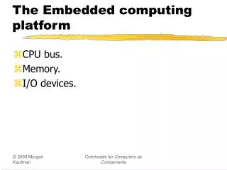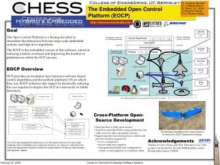
Chapter 4 The Embedded Computing Platform
Chapter 4 The Embedded Computing Platform. 金仲達教授 清華大學資訊工程學系 (Slides are taken from the textbook slides). Outline. CPU Bus and DMA Memory and I/O Devices Component Interfacing Designing with Microprocessors Development, Debugging, Testing Design Example: Alarm Clock. CPU bus.

Chapter 4 The Embedded Computing Platform
E N D
Presentation Transcript
Chapter 4The Embedded Computing Platform 金仲達教授 清華大學資訊工程學系 (Slides are taken from the textbook slides)
Outline • CPU Bus and DMA • Memory and I/O Devices • Component Interfacing • Designing with Microprocessors • Development, Debugging, Testing • Design Example: Alarm Clock
CPU bus • Connects CPU to memory and device • Bus protocol controls communication between entities • decides who gets to use bus at any particular time • governs length, style of communication • Four-cycle handshake: • Basis of many bus protocols • 2 wires: enq (enquiry) and ack (acknowledgment) enq dev1 dev2 data ack
1 3 2 4 Four-cycle example enq data ack time
Memory Typical bus signals • Clock • R/W’: true when bus is reading • Address: a-bit bundle • Data: n-bit bundle • Data ready’ Device 1 Device 2 Clock CPU R/W’ Address Data ready’ Data
one rising falling zero 10 ns stable changing Timing diagrams A B timing constraint C time
Transaction types • Wait state: • state in a bus transaction to wait for acknowledgment • Disconnected transfer: • bus is freed during wait state • request and response are separate • Burst: • multiple transfers • need an extra line called burst’
bus grant Device DMAC bus request CPU Memory DMA • Direct Memory Access: a bus operation not controlled by CPU • Controlled by DMA controller (a bus master) • 2 additional wires • Bus request & Bus grant
DMA Operation • CPU controls DMA operation with 3 registers in DMAC • Starting address register • Length register • Status register • DMAC operation mode: • Burst mode: CPU stalls until I/O completes • Cycle-stealing mode: DMAC releases bus after each unit of transfer
CPU low-speed bus high-speed bus Low-speed Device Low-speed Device Memory Bridge High-speed device System Bus Configuration • The bridge: • A slave on the fast bus • The master of the slow bus
Bridge ARM Bus AMBA high-performance bus (AHB) SRAM ARM CPU Low-speed I/O device External DRAM controller High-speed I/O device Low-speed I/O device AMBA peripherals bus (APB) System-on-Chip
Outline • CPU Bus and DMA • Memory and I/O Devices • Component Interfacing • Designing with Microprocessors • Development, Debugging, Testing • Design Example: Alarm Clock
CE’ R/W’ RAS’ CAS’ Adrs Data DRAM RAM: Random-Access Memory • SRAM (Static RAM) and DRAM (Dynamic RAM) • DRAM: values must be periodically refreshed; addressed by row and column addresses • Page mode, synchronous DRAM, video RAM Clock CE’ CE’ R/W’ R/W’ RAS’ Adrs CAS’ Adrs Data Data SDRAM SRAM
ROM: Read-Only Memory • Factory-programmed ROM • Field-programmed ROM (with ROM burners) • Antifuse-programmable ROM (programmed once) • UV-erasble PROM (aka UV-EPROM) (multiple times) • Flash PROM: modern form of EPROM • Old time: need to be removed from the system and must be erased in entirety • Current time: can be upgraded inside the system and erased in blocks (aka boot-block flash)
Timers and counters • Very similar: • a timer is incremented by a periodic signal; • a counter is incremented by an asynchronous, occasional signal. • Rollover causes interrupt • Watchdog timer: • Periodically reset by system timer • If is not reset, an interrupt to reset the host host CPU interrupt watchdog timer reset
R Vout bn encoder Vin 2R bn-1 4R bn-2 8R bn-3 ... A/D and D/A converters • Analog/digital converter (ADC) • Sampling the analog input before converting it to digital form • Triggered by a control signal • Digital/analog converter (DAC)
Keyboards • An array of switches • Switch debouncing: • A switch must be debounced to multiple contacts caused by eliminate mechanical bouncing
Encoded keyboard • An array of switches is read by an encoder • row address and column output used for encodong • N-key rollover remembers multiple key depressions. row scan
LED • Must use resistor to limit current: • An on LED has only 0.7V voltage drop digital logic current-limiting resistor LED
7-segment LCD display • May use parallel or multiplexed input.
Types of high-resolution display • Cathode ray tube (CRT) • Liquid crystal display (LCD) • Plasma, etc.
voltage Touchscreen • Includes input and output device. • Input device is a two-dimensional voltmeter for position sensing: ADC
Outline • CPU Bus and DMA • Memory and I/O Devices • Component Interfacing • Designing with Microprocessors • Development, Debugging, Testing • Design Example: Alarm Clock
Outline • CPU Bus and DMA • Memory and I/O Devices • Component Interfacing • Designing with Microprocessors • Development, Debugging, Testing • Design Example: Alarm Clock
Designing with microprocessors • Architectures and components: • software; • hardware. • Debugging. • Manufacturing testing.
Hardware platform architecture • There are several components in HW • CPU • bus • memory • I/O devices: networking, sensors, actuators, etc. • How to implement an embedded system using these components?
Software architecture • Functional description must be broken into pieces – partitioning • division among people • conceptual organization • performance • testability • maintenance • Software doesn’t run without hardware • How much hardware you need is determined by the software requirements • speed • memory
Evaluation boards • Designed by CPU manufacturer or others • Includes CPU, memory, some I/O devices • May include prototyping section • CPU manufacturer often gives out evaluation board (e.g., EV board) • can be used as starting point for your custom board design.
Adding logic to a board • Programmable logic devices (PLDs) • provide low/medium density logic • Field-programmable gate arrays (FPGAs) • provide more logic and multi-level logic • Application-specific integrated circuits (ASICs) are manufactured for a single purpose
The PC as a platform • Advantages: • cheap and easy to get • rich and familiar software environment • Disadvantages: • requires a lot of hardware resources • not well-adapted to real-time
Typical PC hardware platform CPU memory device CPU bus bus interface high-speed bus DMA controller intr ctrl timers low-speed bus bus interface device
Typical PC busses • ISA (Industry Standard Architecture) • original IBM PC bus, low-speed by today’s standard • PCI: standard for high-speed interfacing • 33 or 66 MHz • 264 MB/sec or 524 MB/sec • USB (Universal Serial Bus), Firewire, 1394 • relatively low-cost serial interface with high speed
Software elements • IBM PC uses BIOS (Basic I/O System) to implement low-level functions: • boot-up; • minimal device drivers. • BIOS has become a generic term for the lowest-level system software.
Example: StrongARM SA-1100 (1/2) • StrongARM SA-1100 system includes: • CPU chip (3.686 MHz clock) • system control module (32.768 kHz clock) • Real-time clock • operating system timer • general-purpose I/O • interrupt controller • power manager controller • reset controller
Example: StrongARM SA-1100 (2/2) ARM CPU core 3.686 MHz clock 32.768 kHz clock System control module system bus Bridge peripheral bus
Outline • CPU Bus and DMA • Memory and I/O Devices • Component Interfacing • Designing with Microprocessors • Development, Debugging, Testing • Design Example: Alarm Clock
serial port CPU Host system Target system Host vs. Target • Host: a PC or workstation for development • Target: the HW on which the code will run • Cross-compiler: one that runs on host but generates code for target
Debugging embedded systems • Challenges: • target system may be hard to observe • target may be hard to control • may be hard to generate realistic inputs • setup sequence may be complex
Software debuggers • A monitor program residing on target provides basic debugger functions • Debugger should have a minimal footprint in memory • User program must be careful not to destroy debugger program, but , should be able to recover from some damage caused by user code
Breakpoints • A breakpoint allows the user to stop execution, examine system state, and change state. • Replace the breakpointed instruction with a subroutine call to the monitor program. • Breakpoint handler actions: • Save registers. • Allow user to examine machine. • Before returning, restore system state. • Safest way to execute the instruction is to replace it and execute in place. • Put another breakpoint after the replaced breakpoint to allow restoring the original breakpoint.
0x400 MUL r4,r6,r6 0x404 ADD r2,r2,r4 0x408 ADD r0,r0,#1 0x40c B loop uninstrumented code 0x400 MUL r4,r6,r6 0x404 ADD r2,r2,r4 0x408 ADD r0,r0,#1 0x40c BL bkpoint code with breakpoint ARM breakpoints
In-circuit emulators (a.k.a. ICE) • A microprocessor in-circuit emulator is a specially-instrumented microprocessor • Inside ICE, there is a special version of the microprocessor that allows its internal registers to be read out when stopped • This special CPU provides as much debugging functionality as a debugger (SW) but does not take out any memory • Disadvantage: one ICE (expensive) is specific to one particular microprocessor (down to pinout)
Logic analyzers • A logic analyzer is an array of low-grade oscilloscopes:
Logic analyzer architecture UUT sample memory microprocessor system clock vector address controller state or timing mode clock gen keypad display
Code verification • Instruction-level simulator • a.k.a. CPU simulator • down to the details in the programming model • NOT simulate the actions of bus or I/O devices • ARM and SHARC have such simulator • Cycle-level simulator • To simulate HW operation of a computer • Hardware/software co-simulator • Most common type of co-verification • Consists of both HW and SW simulator