Download
1 / 53
560 likes | 789 Vues
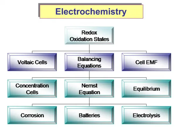
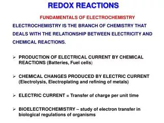
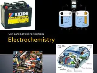
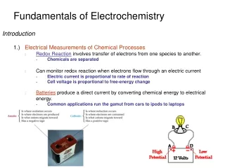
Fundamentals of Electrochemistry. CHEM*7234 / CHEM 720 Lecture 4 INSTRUMENTATION. OHM'S LAW. Ohms law, or more correctly called Ohm's Law, named after Mr. Georg Ohm, German mathematician and physicist (b. 1789 - d. 1854), defines the relationship between voltage, current and resistance.

E N D
Fundamentals of Electrochemistry CHEM*7234 / CHEM 720 Lecture 4 INSTRUMENTATION
OHM'S LAW Ohms law, or more correctly called Ohm's Law, named after Mr. Georg Ohm, German mathematician and physicist (b. 1789 - d. 1854), defines the relationship between voltage, current and resistance.
V = I · R or V / I = R Where: V = Voltage I = Current R = Resistance
Example: I = ? V = I * R I = V / R I = 9 [V] / 18 [Ω] I = 0.5 [A]
Series connection I = I1 = I2 = I3 Vtotal = V1 + V1 + V3 Since V = I R, then Vtotal = I1R1 + I2R2 + I3R3 and Vtotal = I Rtotal Setting both equations equal, we get: I Rtotal = I1R1 + I2R2 + I3R3 We know that the current through each resistor (from the first equation) is just I. so I Rtotal = I(R1 + R2 + R3) Rtotal = R1 + R2 + R3
Parallel connection Kirchhoff’s Current Law states that Itotal = I1 + I2 + I3 from Ohm’s Law Itotal = V1/R1 + V2/R2 + V3/R3 but V1 = V2 = V3 = V and Itotal = V/Rtotal gives us:
Capacitors where: Vc – voltage across the capacitor qc – charge stored C – capacitance
Vc = Xc · Imax (sint - /2) Vc max = XC.Imax • there is 90º difference in phase between current and voltage • Xc is called capacitive reactance • Xc = 1/(C) = 1/(2fC) • Xc – a frequency dependent resistor
Impedance, resistance and reactance • Impedance, Z, is the general name we give to the ratio of voltage to current. • Resistance, R, is a special case of impedance where voltage and current are NOT phase shifted relative to each other. • Reactance, Xc, is an another special case in which the voltage and current are out of phase by 90° Generalized Ohm’s Law V = I · Z
RC circuit Because of the 90º phase shift between VC and VR the resistance and capacitive reactance add according to vector addition !!! so Z2RC = R2 + XC2
Low Pass Filter Vin = ZRC· I and Vout = XC · I
f small XC large Z XC Vout Vin f large XC small XC/Z small Vout 0
High Pass Filter Vin = ZRC· I and Vout = R· I
f small XC large Z XC Vout 0 f large XC small Z R Vout Vin
Band Pass Filter Cascade an LPF and a HPF and you get BPF In practice use Operational Amplifiers to construct a BPF
Why RC circuits? • RC series creates filters • electrochemical cell may be simplified with RC circuit (recall from lecture 2) or, if faradaic process present:
What are they and why do we need them ? Operational Amplifiers (Op-amps) • - very high DC (and to a lesser extent AC) gain amplifiers • proper design of circuits containing Op-amps allows electronic algebraic arithmetic to be performed as well as many more useful applications. • they are essential components of modern-day equipment including your POTENTIOSTAT / GALVANOSTAT !!
General Characteristics • very high input gain (104 to 106) • has high unity gain bandwidth • two inputs and one output • very high input impedance (109 to 1014) • GOLDEN RULE #1 : an Op-amp draws no appreciable current into its input terminals. General Response • Electronically speaking, the output will do whatever is necessary to make the voltage difference between the inputs zero !! • GOLDEN RULE #2
+ 15 V I N P U T S OUTPUT - 15 V - + In op-amps (as in life) you never get anything for free. The gain () is achieved by using power from a power supply (usually 15V). Thus the output of your op-amp can never exceed the power supply voltage !
- - + + Ideal Op-Amp Behaviour • infinite gain ( = ) • Rin = • Rout = 0 • Bandwidth = • The + and – terminals have nothing to do with polarity they simply indicate the phase relationship between the input and output signals.
- V0 + - + Open - loop Configuration Even if + - - 0 then Vo is very large because is so large (ca. 106) Therefore an open-loop configuration is NOT VERY USEFUL.
Rf Rin Vin - V0 S + - + Close-loop Configuration Often it is desirable to return a fraction of the output signal from an operational amplifier back to the input terminal. This fractional signal is termed feedback.
Frequency Response of Op-Amps The op-amp doesn’t respond to all frequencies equally.
- + V0 Vin Voltage Follower Vo = V in Why would this be of any use ? Allows you to measure a voltage without drawing any current – almost completely eliminates loading errors.
Rf - Iin V0 + Current Amplifiers Vo = - Iin Rf
Rf V1 V2 V3 R1 R2 R3 V0 - + Summing Amplifiers
C R V0 Vi - + Integrating Amplifier And if you wanted to integrate currents?
The design of electrochemical experiments • Equilibrium techniques potentiometry, amperometry differential capacitance • Steady state techniques voltammetry, polarography, coulometry and rotating electrodes • Transient techniques chronoamperometry, chronocoulometry, chronopotentiometry In all experiments, precise control or measurements of potential, charge and/or current is an essential requirement of the experiment.
The design of electrochemical cell • Electrodes working electrode(s), counter electrode and reference electrode • Electrolyte • Cell container
Working electrode • most common is a small sphere, small disc or a short wire, but it could also be metal foil, a single crystal of metal or semiconductor or evaporated thin film • has to have useful working potential range • can be large or small – usually < 0.25 cm2 • smooth with well defined geometry for even current and potential distribution
Working electrode - examples • mercury and amalgam electrodes reproducible homogeneous surface, large hydrogen overvoltage. • wide range of solid materials – most common are “inert” solid electrodes like gold, platinum, glassy carbon. reproducible pretreatment procedure, proper mounting
Counter electrodes • to supply the current required by the W.E. without limiting the measured response. • current should flow readily without the need for a large overpotential. • products of the C.E. reaction should not interfere with the reaction being studied. • it should have a large area compared to the W.E. and should ensure equipotentiality of the W.E.
Reference electrode The role of the R.E. is to provide a fixed potential which does not vary during the experiment. A good R.E. should be able to maintain a constant potential even if a few microamps are passed through its surface.
Micropolarisation tests (a) response of a good and (b) bad reference electrode.
Reference electrodes - examples • mercury – mercurous chloride (calomel) the most popular R.E. in aq. solutions; usually made up in saturated KCl solution (SCE); may require separate compartment if chloride ions must be kept out of W.E. • silver – silver halide gives very stable potential; easy to prepare; may be used in non aqueous solutions
The electrolyte solution • it consists of solvent and a high concentration of an ionised salt and electroactive species • to increase the conductivity of the solution, to reduce the resistance between • W.E. and C.E. (to help maintain a uniform current and potential distribution) • and between W.E. and R.E. to minimize the potential error due to the uncompensated solution resistance iRu
Troubleshooting • is there any response? • is the response incorrect or erratic? • is the response basically correct but noisy?