High Level Triggering
High Level Triggering. Fred Wickens. High Level Triggering (HLT). Introduction to triggering and HLT systems What is Triggering What is High Level Triggering Why do we need it Case study of ATLAS HLT (+ some comparisons with other experiments) Summary.


High Level Triggering
E N D
Presentation Transcript
High Level Triggering Fred Wickens
High Level Triggering (HLT) • Introduction to triggering and HLT systems • What is Triggering • What is High Level Triggering • Why do we need it • Case study of ATLAS HLT (+ some comparisons with other experiments) • Summary
Dead time • Experiments frozen from trigger to end of readout • Trigger rate with no deadtime = R per sec. • Dead time / trigger = t sec. • For 1 second of live time = 1 + Rt seconds • Live time fraction = 1/(1 + Rt) • Real trigger rate = R/(1 + Rt) per sec.
Trigger systems 1980’s and 90’s • bigger experiments more data per event • higher luminosities more triggers per second • both led to increased fractional deadtime • use multi-level triggers to reduce dead-time • first level - fast detectors, fast algorithms • higher levels can use data from slower detectors and more complex algorithms to obtain better event selection/background rejection
Trigger systems 1990’s and 2000’s • Dead-time was not the only problem • Experiments focussed on rarer processes • Need large statistics of these rare events • But increasingly difficult to select the interesting events • DAQ system (and off-line analysis capability) under increasing strain - limiting useful event statistics • This is a major issue at hadron colliders, but is also significant at ILC • Use the High Level Trigger to reduce the requirements for • The DAQ system • Off-line data storage and off-line analysis
Summary of ATLAS Data Flow Rates • From detectors > 1014 Bytes/sec • After Level-1 accept ~ 1011 Bytes/sec • Into event builder ~ 109 Bytes/sec • Onto permanent storage ~ 108 Bytes/sec ~ 1015 Bytes/year
Level 1 (Sometimes called Level-0 - LHCb) • Time: one very few microseconds • Standard electronics modules for small systems • Dedicated logic for larger systems • ASIC - Application Specific Integrated Circuits • FPGA - Field Programmable Gate Arrays • Reduced granularity and precision • calorimeter energy sums • tracking by masks • Event data stored in front-end electronics (at LHC use pipeline as collision rate shorter than Level-1 decision time)
Level 2 • 1) few microseconds (10-100) • hardwired, fixed algorithm, adjustable parameters • 2) few milliseconds (1-100) • Dedicated microprocessors, adjustable algorithm • 3-D, fine grain calorimetry • tracking, matching • Topology • Different sub-detectors handled in parallel • Primitives from each detector may be combined in a global trigger processor or passed to next level
Level 2 - cont’d • 3) few milliseconds (10-100) - 2006 • Processor farm with Linux PC’s • Partial events received with high-speed network • Specialised algorithms • Each event allocated to a single processor, large farm of processors to handle rate • If separate Level 2 data from each event stored in many parallel buffers (each dedicated to a small part of the detector)
Level 3 • millisecs to seconds • processor farm • microprocessors/emulators/workstations • Now standard server PC’s • full or partial event reconstruction • after event building (collection of all data from all detectors) • Each event allocated to a single processor, large farm of processors to handle rate
Summary of Introduction • For many physics analyses, aim is to obtain as high statistics as possible for a given process • We cannot afford to handle or store all of the data a detector can produce! • What does the trigger do • select the most interesting events from the myriad of events seen • I.e. Obtain better use of limited output band-width • Throw away less interesting events • Keep all of the good events(or as many as possible) • But note must get it right - any good events thrown away are lost for ever! • High level trigger allows much more complex selection algorithms
Case study of the ATLAS HLT system Concentrate on issues relevant forATLAS (CMS very similar issues), but try to address some more general points
Starting points for any HLT system • physics programme for the experiment • what are you trying to measure • accelerator parameters • what rates and structures • detector and trigger performance • what data is available • what trigger resources do we have to use it
Physics at the LHC Interesting events are buried in a seaof soft interactions B physics High energy QCD jet production top physics Higgs production
The LHC and ATLAS/CMS • LHC has • design luminosity 1034 cm-2s-1 (In 2008 from 1031 - 1033 ?) • bunch separation 25 ns (bunch length ~1 ns) • This results in • ~ 23 interactions / bunch crossing • ~ 80 charged particles (mainly soft pions) / interaction • ~2000 charged particles / bunch crossing • Total interaction rate 109 sec-1 • b-physics fraction ~ 10-3 106 sec-1 • t-physics fraction ~ 10-8 10 sec-1 • Higgs fraction ~ 10-11 10-2 sec-1
Physics programme • Higgs signal extraction important but very difficult • Also there is lots of other interesting physics • B physics and CP violation • quarks, gluons and QCD • top quarks • SUSY • ‘new’ physics • Programme will evolve with: luminosity, HLT capacity and understanding of the detector • low luminosity (first ~2 years) • high PT programme (Higgs etc.) • b-physics programme (CP measurements) • high luminosity • high PT programme (Higgs etc.) • searches for new physics
Trigger strategy at LHC • To avoid being overwhelmed use signatures with small backgrounds • Leptons • High mass resonances • Heavy quarks • The trigger selection looks for events with: • Isolated leptons and photons, • -, central- and forward-jets • Events with high ET • Events with missing ET
~ 200 Hz Physics ~ 300 MB/s ARCHITECTURE Trigger DAQ ~1 PB/s(equivalent) 40 MHz Three logical levels Hierarchical data-flow LVL1 - Fastest:Only Calo and MuHardwired On-detector electronics: Pipelines ~2 ms LVL2 - Local:LVL1 refinement +track association Event fragments buffered in parallel ~10 ms LVL3 - Full event:“Offline” analysis Full event in processor farm ~1 sec.
Trigger design - Level-1 • Level-1 • sets the context for the HLT • reduces triggers to ~75 kHz • has a very short time budget • few micro-sec (ATLAS/CMS ~2.5 - much used up in cable delays!) • Detectors used must provide data very promptly, must be simple to analyse • Coarse grain data from calorimeters • Fast parts of muon spectrometer (I.e. not precision chambers) • NOT precision trackers - too slow, too complex • (LHCb does use some simple tracking data from their VELO detector to veto events with more than 1 primary vertex) • Proposed FP420 detectors provide data too late
ATLAS Level-1 trigger system • Calorimeter and muon • trigger on inclusive signatures • muons; • em/tau/jet calo clusters; missing and sum ET • Hardware trigger • Programmable thresholds • Selection based on multiplicities and thresholds
ATLAS em cluster trigger algorithm “Sliding window” algorithm repeated for each of ~4000 cells
ATLAS Level 1 Muon trigger RPC - Trigger Chambers - TGC Measure muon momentum with very simple tracking in a few planes of trigger chambers RPC: Restive Plate Chambers TGC: Thin Gap ChambersMDT: Monitored Drift Tubes
Level-1 Selection • The Level-1 trigger - an “or” of a large number of inclusive signals - set to match the current physics priorities and beam conditions • Precision of cuts at Level-1 is generally limited • Adjust the overall Level-1 accept rate (and the relative frequency of different triggers) by • Adjusting thresholds • Pre-scaling (e.g. only accept every 10th trigger of a particular type) higher rate triggers • Can be used to include a low rate of calibration events • Menu can be changed at the start of run • Pre-scale factors may change during the course of a run
Trigger design - Level-2 • Level-2 reduce triggers to ~2 kHz • Note CMS does not have a physically separate Level-2 trigger, but the HLT processors include a first stage of Level-2 algorithms • Level-2 trigger has a short time budget • ATLAS ~10 milli-sec average • Note for Level-1 the time budget is a hard limit for every event, for the High Level Trigger it is the average that matters, so a some events can take several times the average, provided thay are a minority • Full detector data is available, but to minimise resources needed: • Limit the data accessed • Only unpack detector data when it is needed • Use information from Level-1 to guide the process • Analysis proceeds in steps with possibility to reject event after each step • Use custom algorithms
Regions of Interest • The Level-1 selection is dominated by local signatures (I.e. within Region of Interest - RoI) • Based on coarse granularity data from calo and mu only • Typically, there are 1-2 RoI/event • ATLAS uses RoI’s to reduce network b/w and processing power required
Trigger design - Level-2 - cont’d • Processing scheme • extract features from sub-detector data in each RoI • combine features from one RoI into object • combine objects to test event topology • Precision of Level-2 cuts • Emphasis is on very fast algorithms with reasonable accuracy • Do not include many corrections which may be applied off-line • Calibrations and alignment available for trigger not as precise as ones available for off-line
Trigger DAQ Calo MuTrCh Other detectors ~ 1 PB/s 40 MHz 40 MHz LVL1 2.5 ms LVL1 accept Calorimeter Trigger Muon Trigger ROD ROD ROD Read-Out Drivers 75 kHz 120 GB/s Read-Out Links RoI’s LVL2 RoI requests ROB ROB ROB ~ 10 ms ROS Read-Out Buffers ROIB L2SV Read-Out Sub-systems RoI data = 1-2% ~2 GB/s L2P L2P L2P ~2 kHz ~3 GB/s L2N LVL2 accept Event Builder Event Filter ~ 1 sec EB ~3 GB/s EFN EFP EFP EFP ~ 300 MB/s ~ 200 Hz ~ 300 MB/s ARCHITECTURE FE Pipelines 2.5 ms H L T
CMS Event Building • CMS perform Event Building after Level-1 • This simplifies the architecture, but places much higher demand on technology: • Network traffic ~100 GB/s • Use Myrinet instead of GbE for the EB network • Plan a number of independent slices with barrel shifter to switch to a new slice at each event • Time will tell whichphilosophy is better
Signature + e30i e30i Iso– lation Iso– lation STEP 4 Signature + e30 e30 pt> 30GeV pt> 30GeV STEP 3 Signature t i m e e + e track finding track finding STEP 2 Signature ecand ecand + Cluster shape Cluster shape STEP 1 Level1 seed + EM20i EM20i Example for Two electron trigger LVL1 triggers on two isolated e/m clusters with pT>20GeV (possible signature: Z–>ee) HLT Strategy: • Validate step-by-step • Check intermediate signatures • Reject as early as possible Sequential/modular approach facilitates early rejection
Trigger design - Event Filter / Level-3 • Event Filter reduce triggers to ~200 Hz • Event Filter budget ~ 1 sec average • Full event detector data is available, but to minimise resources needed: • Only unpack detector data when it is needed • Use information from Level-2 to guide the process • Analysis proceeds in steps with possibility to reject event after each step • Use optimised off-line algorithms
Electron slice at the EF Wrapper of CaloRec TrigCaloRec EFCaloHypo Wrapper of newTracking EF tracking matches electromagnetic clusters with tracks and builds egamma objects EFTrackHypo Wrapper of EgammaRec TrigEgammaRec EFEgammaHypo
Trigger design - HLT strategy • Level 2 • confirm Level 1, some inclusive, some semi-inclusive,some simple topology triggers, vertex reconstruction(e.g. two particle mass cuts to select Zs) • Level 3 • confirm Level 2, more refined topology selection,near off-line code
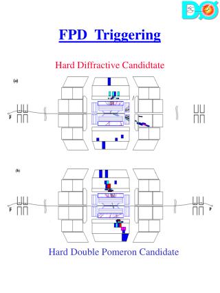
Example B-physics Menu for 10^33 LVL1 : • MU6 rate 24kHz (note there are large uncertainties in cross-section) • In case of larger rates use MU8 => 1/2xRate • 2MU6 LVL2: • Run muFast in LVL1 RoI ~ 9kHz • Run ID recon. in muFast RoI mu6 (combined muon & ID) ~ 5kHz • Run TrigDiMuon seeded by mu6 RoI (or MU6) • Make exclusive and semi-inclusive selections using loose cuts • B(mumu), B(mumu)X, J/psi(mumu) • Run IDSCAN in Jet RoI, make selection for Ds(PhiPi) EF: • Redo muon reconstruction in LVL2 (LVL1) RoI • Redo track reconstruction in Jet RoI • Selections for B(mumu) B(mumuK*) B(mumuPhi), BsDsPhiPi etc.
Background Off-line Physics channel On-line Matching problem
Matching problem (cont.) • ideally • off-line algorithms select phase space which shrink-wraps the physics channel • trigger algorithms shrink-wrap the off-line selection • in practice, this doesn’t happen • need to match the off-line algorithm selection • For this reason many trigger studies quote trigger efficiency wrt events which pass off-line selection • BUT off-line can change algorithm, re-process and recalibrate at a later stage • SO, make sure on-line algorithm selection is well known, controlled and monitored
Selection and rejection • as selection criteria are tightened • background rejection improves • BUT event selection efficiency decreases
Selection and rejection • Example of a recent ATLAS Event Filter (I.e. Level-3) study of the effectiveness of various discriminants used to select 25 GeV electrons from a background of dijets
Other issues for the Trigger • Efficiency and Monitoring • In general need high trigger efficiency • Also for many analyses need a well known efficiency • Monitor efficiency by various means • Overlapping triggers • Pre-scaled samples of triggers in tagging mode (pass-through) • Final detector calibration and alignment constants not available immediately - keep as up-to-date as possible and allow for the lower precision in the trigger cuts when defining trigger menus and in subsequent analyses • Code used in trigger needs to be very robust - low memory leaks, low crash rate, fast • Beam conditions and HLT resources will evolve over several years (for both ATLAS and CMS) • In 2008 luminosity low, but also HLT capacity will be < 50% of full system (funding constraints)
Summary • High-level triggers allow complex selection procedures to be applied as the data is taken • Thus allow large numbers of events to be accumulated, even in presence of very large backgrounds • Especially important at LHC - but significant at most accelerators • The trigger stages - in the ATLAS example • Level 1 uses inclusive signatures • muons; em/tau/jet calo clusters; missing and sum ET • Level 2 refines Level 1 selection, adds simple topology triggers, vertex reconstruction, etc • Level 3 refines Level 2 adds more refined topology selection • Trigger menus need to be defined, taking into account: • Physics priorities, beam conditions, HLT resources • Include items for monitoring trigger efficiency and calibration • Must get it right - any events thrown away are lost for ever!