Understanding Power Factor: Key Concepts and Calculations for Electrical Systems
The power factor (PF) is a crucial metric representing the portion of apparent power dissipated as true power in electrical systems. It affects current, energy loss, and equipment size, impacting costs for industrial and commercial customers. A low power factor necessitates larger wires, increasing distribution losses and expenses. Automatic power factor correction units utilize capacitors controlled by regulators to maintain optimal PF. Understanding key equations helps solve practical problems, including calculating PF in series circuits, vital for managing electrical efficiency.


Understanding Power Factor: Key Concepts and Calculations for Electrical Systems
E N D
Presentation Transcript
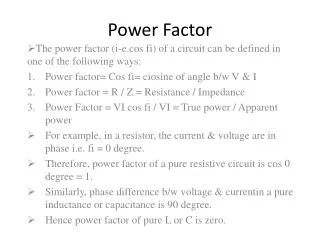
What is the power factor? A number that represents the portion of the apparent power dissipated as true power. (Number represented as a decimal fraction or percentage.) • Eq. 24.22 PF = TP/AP AP= Apparent Power TP= True Power or Real Power
In an electric power system, a load with a low power factor draws more current than a load with a high power factor for the same amount of useful power transferred. • The higher currents increase the energy lost in the distribution system, and require larger wires and other equipment. • Because of the costs of larger equipment and wasted energy, electrical utilities will usually charge a higher cost to industrial or commercial customers where there is a low power factor. • An automatic power factor correction unit consists of a number of capacitor that are switched by means of contactors. These contactors are controlled by a regulator that measures power factor in an electrical network.
More Equations • Substituting the equations for TP and AP in the Power Factor equation will yield: IR2R / IT2Z = PF
For Series Circuits Only!! In series circuits, the current is the same, and IR equals IT. Therefore this power factor equation becomes: • Eq. 24.23 • IR2R / IT2Z R / Z = PF
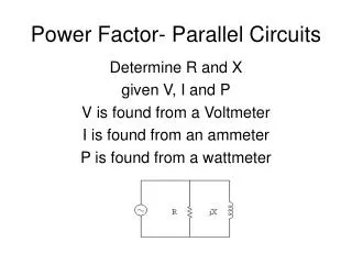
For Parallel Circuits Only Eq. 24.23 is modified as: Eq. 24.24 IR / IZ = PF (Note: IZ = IT)
Eq. 24.25 PF = Cos θ S= Apparent Power P= True Power Q= Reactive Power
Problems • Find the power factor of a series circuit when R=5kΩ, Z=7.07kΩ, θ= 45°, VS= 20V, and IT = 2.82mA
Example Find the power factor of a series circuit when R=5kΩ, Z=7.07kΩ, θ= 45°, VS= 20V, and IT = 2.82mA PF = (2.82mA)2*5kΩ/(2.82mA)2*7.07k Ω = .707 PF = 5kΩ/7.07kΩ = .707 PF = Cos 45° = .707
Last equation to know Combining the previous equations gives us an equation for true power that is universal. Can be used for any type of circuit. • Eq. 24.26 • TP = ITVS Cos θ
Power Factor Correction http://www.allaboutcircuits.com/vol_2/chpt_11/4.html