PHY1013S CAPACITANCE
PHY1013S CAPACITANCE. Gregor Leigh gregor.leigh@uct.ac.za. CAPACITANCE. Recognise, describe, state the uses of, and draw the circuit diagram symbol for capacitors. Determine the capacitance of capacitors (both parallel plate and spherical) from their geometries.

PHY1013S CAPACITANCE
E N D
Presentation Transcript
PHY1013SCAPACITANCE Gregor Leighgregor.leigh@uct.ac.za
CAPACITANCE CAPACITANCE • Recognise, describe, state the uses of, and draw the circuit diagram symbol for capacitors. • Determine the capacitance of capacitors (both parallel plate and spherical) from their geometries. • Determine equivalent capacitances, charges, potential differences, and stored energies in circuits containing various series and parallel combinations of capacitors, with or without dielectrics. Learning outcomes:At the end of this chapter you should be able to…
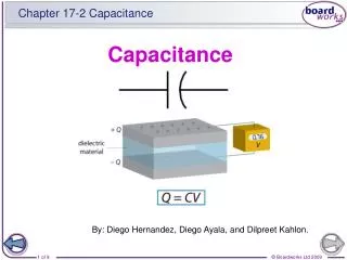
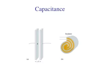
CAPACITORS A capacitor stores charge, which it later releases (causing a current in the opposite direction to that which charged it). This makes it a useful component for, inter alia, storing electrical potential energy. +Q V A d –Q PHY1013S CAPACITANCE A capacitor consists of two isolated conductors placed close together, but not touching. While the conductors can have any shape and configuration, the simplest capacitor has two identical plates of area A, separated by a distance d. The circuit diagram symbol for a capacitor is . 3
CAPACITANCE THE DEFIBRILLATOR paddle During cardiac arrest the heart loses its regular rhythm and begins to fibrillate. patient paddle Delivering a short, sharp burst of electrical energy across the patient’s chest can restore the natural heartbeat.
CAPACITANCE CHARGING A CAPACITOR • Ordinarily, a break in a circuit would prevent charge moving around the circuit, but the opposing plates of a capacitor act as “reservoirs”, allowing a certain amount of charge to be “pumped” from one plate to another. Vb VC As the potential differences around the circuit change, the pumping process slows, eventually stopping once VC = Vbattery. Note: • VC = V , or even justV in some books!
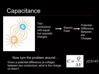
CAPACITANCE CHARGE ON A CAPACITOR • Once a capacitor is charged, its plates carry equal and opposite charges. Although the net charge is therefore zero, we say the capacitor carries a charge Q, equal to the magnitude of the charge on either plate. The charge stored by a capacitor is directly proportional to the potential difference across the plates: Q V Q = CV where the constant C is the capacitance of the capacitor, which depends on the geometry of the plates (notQ/V!). Units: [C/V= farad, F] (Since 1 F is a very large value, capacitances are typically measured in pF or F.)
CAPACITANCE PARALLEL PLATE CAPACITOR d • Neglecting edge effects, or “fringing”, the magnitude of the constant, uniform electric field between the plates (which have a surface charge density of = Q/A) is . Since E is constant, the potential difference is given by a simple integration across the gap between the plates: and, since C = Q/V, (Using this equation, we can now express 0 in more convenient units: 0=8.85 pF/m.)
CAPACITANCE CAPACITOR GEOMETRY The capacitance of a device can be increased by increasing the area of plate overlap, A. A V +Q d –Q d +Q “Sandwiching” one of the plates between two others (as shown) creates a capacitance of . The same effect can be achieved by rolling two plates so that the bottom plate reappears above the top plate: (The plates are prevented from touching by the insertion of dielectrics (qv))
And the potential difference between the electrodes is given by … PHY1013S CAPACITANCE SPHERICAL CAPACITORS Any two opposing electrodes, regardless of their shape, will form a capacitor. –Q E In the case of a positively charged sphere surrounded by a negatively charged shell, the field between the electrodes is that due to a point charge situated at the centre of the sphere: +Q 9
CAPACITANCE SPHERICAL CAPACITORS and ISOLATED SPHERES Integrating E over a path from the outer shell (r = b) to the positive surface (r = a) and using –drin place of ds gives: –Q E a +Q b and, sinceC = Q/V, For an isolated conducting sphere of radius a, we divide through by b and then simply let b in order to derive: C = 40a
V V V V CAPACITANCE CAPACITORS IN PARALLEL • When three capacitors are connected in parallel, the same potential difference is applied across all three, but the charge stored by each capacitor depends on its individual capacitance: C1 –Q1 +Q1 Q1 = C1V, Q2 = C2V, Q3 = C3V C2 –Q2 +Q2 Combining the above we get: Q = Q1 + Q2 + Q3 = (C1 + C2 + C3)V C3 –Q3 +Q3
V V V V CAPACITANCE CAPACITORS IN PARALLEL • Hence the equivalent capacitance Ceq, with the same total charge and applied potential difference, is: C1 –Q1 +Q1 C2 so Ceq = C1 + C2 + C3 –Q2 +Q2 and, in general, for any number of capacitors in parallel: C3 –Q3 +Q3
V V1 V2 V3 V3 V2 V1 CAPACITANCE CAPACITORS IN SERIES • When three capacitors are connected in series, the potential difference across all three is given by the sum of the potential differences across the individual capacitors: +Q1 C1 –Q1 • V = V1 + V2 + V3 +Q2 C2 Because all three capacitors are connected directly together, they all carry the same charge, hence: –Q2 +Q3 C3 Q1 = Q2 = Q3 = Q –Q3
V V1 V2 V3 V1 V2 V3 CAPACITANCE CAPACITORS IN SERIES …and, sinceC = Q/V, +Q1 C1 so –Q1 and, in general, for any number of capacitors in series: +Q2 C2 –Q2 +Q3 A useful simplification for onlytwo capacitors in series is: C3 –Q3
CAPACITANCE 12 V A 12 V battery of negligible resistance is connected to a combination of four capacitors as shown. Calculate: 4 F 12 F • the total capacitance of the circuit; • the total charge stored in the fully charged circuit; • the charge on the 4 F capacitor. 6 F 3 F 6 F 2 F (a) C2+4 = C1 + C2 = 2 + 4 = 6 F
CAPACITANCE 12 V A 12 V battery of negligible resistance is connected to a combination of four capacitors as shown. Calculate: 4 F 12 F • the total capacitance of the circuit; • the total charge stored in the fully charged circuit; • the charge on the 4 F capacitor. 3 F 6 F 4 F Qtotal = CtotalVtotal = 4 12 = 48 C (b)
CAPACITANCE 12 V A 12 V battery of negligible resistance is connected to a combination of four capacitors as shown. Calculate: 4 F 12 F • the total capacitance of the circuit; • the total charge stored in the fully charged circuit; • the charge on the 4 F capacitor. 6 F 3 F 6 F Qparallel = Q12 = Qtotal = 48 C (c) Q4 = C4V4 = 4 8 = 32 C
CAPACITANCE ENERGY STORED IN A CAPACITOR • Work is done by an external agent (e.g. a battery) to charge a capacitor. Vb Energy stored=Work done. The transfer of each successive unit of charge becomes more and more difficult (!?) VC At some point in the charging process the charge on the capacitor is q, and the potential difference across it is V. To increase the charge by an additional dq requires
CAPACITANCE ENERGY STORED IN A CAPACITOR • Thus the total energy transferred from the battery to the capacitor to raise its charge from zero to Q is: Hence: and, sinceQ = CV: U = ½QV [cf: ] Us = ½k(s)2 U = ½C(V)2 and: (The last being the most practical formula.)
CAPACITANCE THE ENERGY IN THE ELECTRIC FIELD C1 Now consider two equally charged capacitors, C1 and C2, identical except that C2 has twice the plate separation… C2 Since , C2 has half the capacitance and (since ) C2 has twice the stored energy. And sinceE1 = E2, C2 has twice the electric field volume… I.e. The potential energy of a charged capacitor may thus be regarded as being stored in the electric field between its plates. A d
CAPACITANCE ENERGY DENSITY OF AN ELECTRIC FIELD • The amount of energy stored per unit volume is called the energy density of the electric field, uE: Units: [J/m3] (uE is uniform wherever E is uniform) Thus: This expression is valid for any electric field, irrespective of its source or geometry, so… Wherever an electric field exists in space, there is also an associated electric potential energy of magnitude ½0E2 per unit volume.
– – – – – – – – – – – + + + + + + + + + + + CAPACITANCE CAPACITOR WITH A DIELECTRIC • Introducing an insulator, or dielectric, into the space between the plates of an isolated capacitor… • polarises the dielectric • weakens the electric field between the plates by a factor : • lowers the voltage between the plates by a factor : • increases the capacitance of the capacitor by a factor : * • * …but raises the operating voltage of the capacitor
CAPACITANCE CAPACITOR WITH A DIELECTRIC • is the dielectric constant of the introduced material. In a region completely filled by a dielectric material, all electrostatic equations containing the permittivity constant 0 should be modified by replacing 0 with 0. (which is always > 1)is therefore often referred to as… the relative permittivity of the introduced material. Air 1.00054 Paper 3.5 Strontium titanate 310
CAPACITANCE 12 V A 12 V battery of negligible resistance is connected to a combination of four capacitors as shown. Calculate: 48 C 32 C 4 F 12 F • the total capacitance of the circuit; • the total charge stored in the fully charged circuit; • the charge on the 4 F capacitor; • the energy stored in the 3 F capacitor. 3 F 6 F Q3 = Q6 = 48 – 32 = 16 C (d)
CAPACITOR WITH A PARTIAL DIELECTRIC In the event that the dielectric does not completely fill the gap between the plates, the effective capacitance may be calculated by regarding the various regions as separate capacitors combined in series and/or parallel. PHY1013S CAPACITANCE Regions (a) and (b) are in series with each other… (a) …and these two regions are together in parallel with region (c). (c) (b) 25