Download
1 / 54
580 likes | 994 Vues
Fast ignition Laser Fusion Reactor KOYO-F - Summary from design committee of FI laser fusion reactor -. T. Norimatsu Institute of Laser Engineering, Osaka University IFE Forum Presented at US-Japan workshop on Power Plant Studies and related Advanced Technologies with EU participation.

E N D
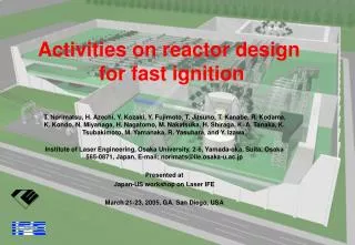
Fast ignition Laser Fusion Reactor KOYO-F- Summary from design committee of FI laser fusion reactor - T. Norimatsu Institute of Laser Engineering, Osaka University IFE Forum Presented at US-Japan workshop on Power Plant Studies and related Advanced Technologies with EU participation
After the Roadmap committee, we organized a conceptual design committee to make the issue clear.In total, 34 working group meetings were held from March 2004 to Sep. 2005. • Chair; A. Tomabechi • Co-chair; Y. Kozaki (IFE, Forum) T. Norimatsu (ILE, Osaka) Core plasma Working Group H. Azechi (ILE, Osaka) K. Mima (ILE, Osaka) Y. Nakao (Kyushu U.) H. Sakagami (Hyogo U.) H. Shiraga (ILE, Osaka) R. Kodama (ILE, Osaka) H. Nagatomo (ILE, Osaka) T. Jhozaki (ILE, Osaka) Laser Working Group N. Miyanaga (ILE, Osaka) K. Ueda (U. Elec.Com.) Y. Owadano (Nat. I. Adv. Ind. Sci.) M. Nakatsuka (ILE, Osaka.) K. Yoshida (Osaka) H. Nakano (Kinki U.) H. Kubomura (Hamamatsu Co.) K. Kawashima (Hamamatsu Co) Y. Suzuki (Laser Front Tech.) T. Jitsuno (ILE, Osaka) H. Fujita (ILE, Osaka) J. Kawanaka (ILE, Osaka) T. Kanabe (Fukui U.) Y. Fujimoto ( ILE, Osaka) K. Tsubakimoto (ILE, Osaka) Y. Furukawa (ILE, Osaka) Target Working Group T. Norimatsu (ILE, Osaka) A. Iwamoto (NIFS) T. Endo (Hiroshima U.) H. Yoshida (Gifu U.) M. Nishikawa (Kyushu U.) S. Konishi (Kyoto U.) Plant system Working Group Y. Kozaki (IFE, Forum) Y. Ueda (Osaka U.) K. Okano (Cent. Res. Ins.) T. Kunugi (Kyoto U.) Y. Sakawa (Nagoya U.) H. Nakano (Kinki U.) A. Sagara (NIFS) Y. Soman (Mitsubishi Co) M. Nishikawa (Kyushu U.) Hayashi (JAERI) H. Furukawa (ILE, Osaka) M. Nakai (ILE, Osaka) T. Kanabe (Fukui U.) Y. Fujimoto ( ILE, Osaka) K. Tsubakimoto (ILE, Osaka) Y. Furukawa (ILE, Osaka) The committee is supported by IFE Forum and ILE, Osaka Univ.
Outline • Introduction • Fast ignition • Gain estimation and the emission • Chamber and plant system • Laser system • Fueling system
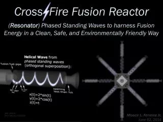
rh rh < rc/4 rc Fast ignition is attractive , because the gain is high with a small laser Processes for compression and ignition are separated. Laser irradiation Compression Ignition Burn Central ignition Fast Ignition 100 Required gain for reactor KOYO (Osaka design) Fusion Gain US-NIF Fast ignition 10 PW laser Central Ignition Fast heating of compressed fuel 1 to create a hot spot at its edge 1 0.1 10 Laser Energy ( ) MJ Fast heating needs petawatt laser. Critical issue is relativistic dense electron dynamics. rh < rc/4 rh ~ rc rc
FIREX-1 project has been started to demonstrate Ti = 5 keV. Gekko XII laser LFEX laser 5
600 times liquid density and 1keV heating have been demonstrated
Two-D simulation checked by implosion experiments at Rochester Univ. indicated that high density compression of reactor-scale, cone target is possible. ILE, GA, Rochester collaboration One of key requirements to start FIREX-II is satisfied.
Although dynamics of cone-guided implosion is quite different from conventional spherical one, high R for ignition can be achieved • existence of the cone causes • non-symmetric • slip boundary • ablated plasma • implosion velocity • shock hits the surface of the cone • timing of maximum density • hot spot ILE Osaka
High gain will be achieved by increasing the laser energy at the same intensity. 0.1
Wet wall reactor High-Gain Dry wall reactor FIREX-2 Self-Ignition FIREX-1 Gain, Q Driven-Ignition ELtot [kJ] Fast Ignition Gain Performance r = 300g/cc, a = 2 and 3 Energy coupling; himp = 5% for implosion & hheat = 30% for core heating In high gain region, target gain considerably decreases with increasing adiabat a.
Outline • Introduction • Chamber and plant system • Chamber structure • Pumping • Protection of final optics • Laser system • Fueling system
KOYO-F with 32 beams for compression and one heating beam • Vertically off-set irradiation • Cascade surface flow with mixing channel • SiC panels coated with wetable metal • Tilted first panels to make no stagnation point of ablated vapor • Compact rotary shutters with 3 synchronized disks
LiPb flow Steel vessel The surface flow is mixed with inner cold flow step by step to reduce the surface temperature.
Thermal flow of KOYO-F( One module) 300 MWe 200MJ /shot x 4Hz hther-elec=30%
Z ④ Simulation box ③ 89mm 400mm r ② Core heating region ① 200mm Estimation of Output Energy Structure 200MJ output (~1.2MJ driver; 1.14MJ imp + 71.5kJ heat) Case • Output Power and Energy Spectrum of of a-particles leaking from each boundary ( ① ~ ④ ) • Output Power of Radiation leaking from each boundary ( ① ~ ④ ) • Output Power of Debris (thermal + Kinetic) leaking from each boundary ( ① ~ ④ )
Z ④ Simulation box ③ 511mm 117mm r ② ① 258mm Summary of Burn Properties Input and output energies [MJ] for ~ 200MJ output case Energy [MJ] Heating side (①)Opposite side (④) Driver Energy※1 1.12 Implosion 1.14 Heating 0.0715 Fusion [MJ] 200 Carried out by Neutron※2 160 (80.0%) 12.7 MJ/str12.7 MJ/str Alpha※3 11.8 ( 5.9%) 1.31 MJ/str0.67 MJ/str Debris※4 19.4 ( 9.7%) 2.26 MJ/str1.34 MJ/str Radiation 1.85 ( 0.9%) 0.12 MJ/str 0.15 MJ/str error 6.9 ( 3.4%) Gain 165 ※1 The energy coupling efficiencies of 5% and 30% were assumed for implosion and core heating, respectively. ※2 Neutrons were assumed to be freely and isotropically escaped from the core. ※3 Alpha particle: Leakage/Source = 29.8% (70.2% is deposited inside the core.) ※4 Constitution (energy D:35.5%, T:49.9%, a:14.3% / Number D:43.6%, T:44.5%, a:11.5%)
V=500m/s The speed of ablated vapor 500 m/s at higher density region and 4000 m/s at the front. (This work is on the way. Depends on the model for stoping range.) P 8
Total mass of ablated materials was 6.2 kg/shot including oblique-incidence effect.
Lot of 0.1 mm radius clusters are formed after adiabatic expansion. (Luk’yanchuk, Zeldovich-Raizer Model)
Future work: Hydrodynamic simulation including phase change is necessary to discuss the formation of aerosol. Jet formation Size of evaporated vapor in flight RT instabilities would form larger particles. -->
Four Pb diffusion pumps will be used to keep the chamber less than 5 Pa
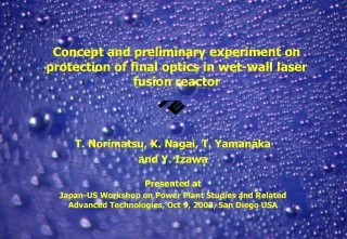
A set of 3 rotary shutters and buffer gas will be used to protect the final optics from the bluster wave.
Vapor coming into the beam duct can be stopped with 0.1Torr D2 buffer gas. 0.5m 100m/s • The speed of vapor is decelerated from 100 m/s to 30 m/s before the plume breaks due to RT instabilities. • Mass of Pb vapor coming into the beam duct is10mg/shot, that means 1 ton/year! Periodic cleaning in necessary.
Outline • Introduction • Fast ignition • Core plasma • Chamber and plant • Laser system • Cooled, ceramic Yb:YAG • Beam distributor • Fueling system
Key technologies of laser for FI fusion plant Foot pulse to form pre-plasma ・32 beams Controlled focus pattern ・2 w ・wide band ・coherent during amplification in-coherent at focus point Main pulse for compression ・32 beams Controlled focus pattern ・3w ・ wide band ・ coherent during amplification low-coherent at focus point Heating pulse ・1beam coherently bundled ・w ・wide band OPCPA ・Pulse compression Grating Lasers 16Hz Distributor Common technologies for compression and heating lasers ・main amplifier laser material, LD Structure, optical shutter ・beam switching Laser:16Hz, reactor:4Hz ・Optics with multi-coating
Cooled Yb:YAG was chosen for the laser material. OPA: Optical Parametric Amplification OPCPA : Optical Parametric Chirp Pulse Amplification
Characteristics of Nd:YAG and Yb:YAG as materials for high power laser Advantage of Yb:YAG Close wavelength of oscillating light to pumping light⇒low heat generation Long fluorescent life time of upper level⇒easy to store energy Wide absorption spectrum⇒ easy to pump with LD Wide fluorescent spectrum⇒short pulse amplification Disadvantage Small cross section for stimulated emission⇒high saturation flounce Quasi three level system⇒energy loss due to re-absorption Life time Heat Heat Life time re-absorption
Why cooled Yb:YAG? Disadvantage Larger cross section for stimulated emission⇒Lower saturation flounce Four level system⇒Higher efficiency with low pumping Higher thermal conductivity ⇒Smaller thermal strength Small cross section for stimulated emission⇒high saturation fluencies Quasi 3 level system⇒Gain loss due to reabsorption ⇒Appropriate characteristics for high intensity, average power laser
Cooled Yb:YAG ceramic is promising as the laser driver material Parasitic osc. limit Damage threshold Small module Optimal area Cooling Thermal shock parameter Thermal fracture 2 Saturation parameter Practical use of ceramic technology Artificial control of emission cross section Cooled Yb:YAG ceramic
Demonstration of high efficiency by cooling Output coupler Yb:YAG LD for pumping Opt-Opt conversion efficiency 74% Pumped area Vacuum vessel Quasi 3 level system 4 level system 4 level system <100K Room Temp.
We demonstrated high beam quality (M2<1.4). Beam quality ビーム品質 M2<1.4 Experimental focusable spot size M= Ideal focusable spot size of Gaussian beam
Estimation of laser efficiency Implosion laser: Total efficiency:11.4% LD eff. = 60%, optical-optical eff. = 30%, (@160K) THG eff. = 70%, transfer eff. = 90% Heating laser: Total efficiency:4.2% LD eff. = 60%, optical-optical eff. = 30%, (@160K) SHG eff. = 80%, OPCPA eff. = 40%, compressor eff. 80%, transfer eff. = 90% Cooling of amplifier: Thermal load of 5% of electric input power to LD Cooling efficiency = 30% (safely assumed, 60%@160K) Total efficiency of laser system includig refriierator= 8.7% (9.2%) • Supplementary power supply (air conditioner, etc.) is excluded • in this estimation. • Improvement of optical-optical eff. is needed.
Cooled Yb:YAG has potential to achieve 20% in electricity to laser efficiency. Current design temperature More explore is necessary in; efficiency of refrigerator, coolant, cross section for stimulated emission, dT/T total cost of optics.
Candidates for amplifier architecture Active mirror Thin disk Zigzag slab Active mirror is practical for arrayed large-aperture amplifier.
Illustration of main amplifier using active mirror concept 8 beams (1/4 of a plant)
Beam distributor Laser beams will be distributed into 4 module reactors using either rotating corner cubes or plasma electorode optical switchs. Plasma-electrode optical switch (LLNL) Rotating corner cube
Outline • Introduction • Chamber and plant • Laser system • Fueling system • Target design • Status of fabrication • Batch process
The cone works as a focusing device of the heating laser. ・Heating laser must be focused on a 30µm diameter spot. ・Heating laser Beam size:2 m×2 m Distance between target and focusing mirror ≈ 50 m ・Accuracy of target injection is not known. →Assistant focusing mechanism is necessary. On axis irradiation 30 mm shifted irradiation Parabola cone Parabola cone スラブ計算
Mass production of target is remaining issue but the elemental researches are promising.
150 Pure DT 10mg/cc Foam 100 Target Gain 30mg/cc Foam 50 0 40 60 80 100 [kJ] E dh Driver Energy for Core Heating, Low density foam is the key of FI target. • When the foam density is 10 mg/cc, the energy of heating laser is increased from 50 kJ to 55 kJ. • Our final goal is to develop 10mg/cc foam shells.(Our achieved data, 43 mg/cc for shell and 5 mg for block) (By Dr. Johzaki et al)
Fuel loading system by thermal cavitation method. Tirtium inventory 100g Not to scale
Hybrid injector for KOYO-F Injection velocity 300+/-2 m/s Rep rate 2 Hz Pointing +/- 1 mm Operation power including freezer 500 kW