ECE331 Lecture 1 9S12Cxx Assembly Language
1.04k likes | 1.08k Vues
Explore the CSM12C128 Evaluation Module and learn about the HC(S)12 programmer’s model, addressing modes, and I/O pins available on the CSMB12C128 module. Understand the processor functionality and memory map of the 9S12Cxxx family. Discover the versatile features and circuit diagrams, including connecting I/O pins to switches and LEDs. Delve into the status register, flag bits, arithmetic flags, and signed overflow detection for addition and subtraction in assembly language programming.

ECE331 Lecture 1 9S12Cxx Assembly Language
E N D
Presentation Transcript
ECE331 Lecture 19S12Cxx Assembly Language CSM12C128 Evaluation Module HC(S)12 Programmer’s (Register) Model HC(S)12 Addressing Modes ECE331 Lecture 1 (KEH)
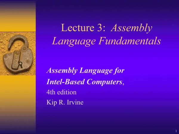
General block diagram for the 9S12Cxxx family ECE331 Lecture 1 (KEH)
Full processor functionality as shown in the block diagram is available with the (relatively expensive) 80-pin Quad Flat Pack (QFP) package. ECE331 Lecture 1 (KEH)
Our CSMB12C128 development module (Designed by Axiom Manufacturing) has a 60-pin external interface. • Unfortunately, it does not plug directly into a breadboard, so a breadboard adapter was made for us by John LaBaio at RHIT Ventures. • Since only 60 pins are available, not all of the 9S12C128 I/O pins are available on our CSMB12C128 module. ECE331 Lecture 1 (KEH)
9S12C128Pins available on CSMB12C128 module. This is the top view of the module pinout. You will need to refer to this page many times as you interface I/O devices throughout this course! ECE331 Lecture 1 (KEH)
CSMB12C128 Module Features ECE331 Lecture 1 (KEH)
A few of the I/O pins that are available: • PA7:0 and PB7:0 – Each of the eight Port A or eight Port B pins may be configured as either a digital input or output. These two ports serve as multiplexed (time-shared) address and data pins when the microcontroller is operated in expanded mode. • PAD7:0 (AN7:0) – Each of the eight “Port AD” pins may be configured as either analog input or as digital input/output. • PT7:0 – Each of the eight “Port T” pins may be configured as timer input capture, timer output compare, or digital input/output. • PM5:0 – “Port M” pins PM5:3 may be configured as digital input or output, in addition, Port M can be used for the following special functions: • PM5:2 => Serial Peripheral Interface (SPI) bus • PM1:0 => CAN serial communication bus Do NOT use PM0 or PM1 for general digital I/O, since these two pins are hardwired to the CAN interface chip on the CSMB12C128 module, and there are no on-board jumpers to break this connection. • PS1:PS0 => These two “PORT S” pins are used as Serial (Asynchronous) Communication Interface (TX and RX) ECE331 Lecture 1 (KEH)
The Inside Story: CSM12C128 Module Circuit Diagram (This diagram is in the class AFS PDF document folder) ECE331 Lecture 1 (KEH)
Connecting two I/O pins to a switch and an LED on the Project Board ECE331 Lecture 1 (KEH)
Wire NEATLY on left side of breadboard– Wires and component leads cut short, pressed down, do not cross over any part. Leave NO chance for short circuits! ECE331 Lecture 1 (KEH)
9S12C128 Memory Map(Note: When the processor is RESET, the 9S12C128 microcontroller’s “RAM position register” is initialized such that RAM is actually mapped to 0x0400 – 0x0FFF) ECE331 Lecture 1 (KEH)
Programmer’s Register Model of CPU12 Core ECE331 Lecture 1 (KEH)
Status Register Flag Bits • Status Register (CCR) = S X H I N Z V C • S = “STOP Instruction Disable Flag” • Out of RESET, this bit is set to 1. • Clearing this flag enables the STOP instruction. • When a STOP instruction executes (if S = 0), the processor’s clock oscillator is shut down, and the processor enters a low-power consumption “Sleep Mode” until the processor is awakened by an interrupt or a RESET event. ECE331 Lecture 1 (KEH)
X-bit - Nonmaskable Interrupt Mask Bit • Out of RESET, X = 1. • Clearing X enables interrupts on the XIRQ* interrupt input line. • Once cleared, the X bit CANNOT be reset by software to disable XIRQ interrupts. Thus the XIRQ input is said to be “non-maskable”.) • The only way to set X = 1 is via RESET. • I-bit - Maskable Interrupt Mask Bit • Out of RESET, I = 1. • Clearing I (via the CLI instruction) enables interrupts on the IRQ* interrupt input line. • The I bit CAN be set back to 1 at any time by the software via the SEI instruction. Thus the IRQ input is said to be maskable. ECE331 Lecture 1 (KEH)
Arithmetic Flags Z N C V H Z …. Zero Flag Set if result = 0 N …. Negative Flag Indicates sign of result (1 => negative, 0 => pos) Follows MSB of result C …. Carry Flag Set if Carry occurs during addition operation Set if Borrow occurs during subtract or compare operation V …. Overflow Flag Set if two’s complement overflow occurs H …. Half Carry Flag Set if carry out of Bit #3 occurs during add operation Not affected by subtract or compare operations ECE331 Lecture 1 (KEH)
Signed(Two’s Complement) Overflow Detection For Addition If addend and augend are of unlike signs => no overflow possible (V=0). If addend and augend are of like sign, and the sign bit of resulting sum disagrees =>overflow (V=1). ECE331 Lecture 1 (KEH)
For Subtraction If subtrahend and subtractor are of like sign => no overflow possible (V = 0). If subtrahend and subtractor are of unlike signs, and the sign bit of the resulting difference is NOT consistent with (a) pos – neg should = pos; (b) neg – pos should = neg) => overflow (V = 1). ECE331 Lecture 1 (KEH)
Flag Setting ExamplesExample #1 LDAA #$38 ADDA #$A9 => $38 + $A9 = $E1 (A contains $E1) H = 1 (carry out of lower 4 bit nybble). C = 0 (no carry out of MSB of result) Z = 0 (result not 0) N = 1 (result negative) V = 0 (adding numbers of opposite sign => no overflow is possible.) ECE331 Lecture 1 (KEH)
Example #2 LDAA #$9A ADDA #$A9 => $9A + $A9 = $43 (A contains $43) H = 1 (carry out of lower 4 bit nybble. C = 1 (carry out of MSB of result) Z = 0 (result not 0) N = 0 (result positive) V = 1 (adding two negative numbers, and sum is positive => overflow) ECE331 Lecture 1 (KEH)
Example #3 LDAA #$FC ADDA #$04 => $FC + $04 = $00 (A contains $00) H = 1 (carry out of lower 4 bit nybble. C = 1 (carry out of MSB of result) Z = 1 (result is 0) N = 0 (result positive) V = 0 (Adding numbers of unlike sign => no overflow is possible.) ECE331 Lecture 1 (KEH)
Example #4 LDAA #$FC SUBA #$04 => $FC - $04 = $F8 (A contains $F8) H = X (H is not affected by subtract or compare, X simply remains in the state it was in.) C = 0 (no borrow out of MSB was requested) Z = 0 (result is not 0) N = 1 (result negative) V = 0 (neg – pos = neg => no overflow). ECE331 Lecture 1 (KEH)
Example #5 LDAA #$70 SUBA #$80 => $70 - $80 = $F0 (A contains $F0) H = X (H is not affected by subtract or compare, X simply remains in the state it was in.) C = 1 (Borrow out of MSB was requested) Z = 0 (result is not 0) N = 1 (result negative) V = 1 (pos – neg = neg => overflow). ECE331 Lecture 1 (KEH)
Example #6 LDAA #$80 CMPA #$70 => $80 - $70 = $10 (But A contains $80 because CMPA does NOT alter A!) H = ? (H is not affected by subtract or compare, H simply remains in the state it was in.) C = 0 (No borrow out of MSB was requested) Z = 0 (result is not 0) N = 0 (result positive) V = 1 (neg – pos = pos => overflow). ECE331 Lecture 1 (KEH)
Example #7 LDAA #$E2 CMPA #$E2 => $E2 - $E2 = 0 (BUT A contains $E2) H = ? (H is not affected by subtract or compare, H simply remains in the state it was in.) C = 0 (NO Borrow out of MSB was requested) Z = 1 (result is 0) N = 0 (result positive) V = 0 (overflow not possible when subtracting numbers of like sign) ECE331 Lecture 1 (KEH)
Addressing Modes – Tell the processor where to find data.1. Immediate Addressing Requires “#” prefix in front of the immediate operand In this addressing mode the data itself is placed IMMEDIATELY after the instruction OP CODE in program memory. Ex: Mem Instr Immed. Addr OpCd Operand Assy Code (hex) (hex) (hex) 4000 86 40 LDAA #64 ;without preceding “$” ;a value defaults to decimal 4002 86 64 LDAA #$64 4004 CE 00 64 LDX #$64 ;X is 16-bit reg, ;so 2 bytes data needed LBL: EQU $1234 ;LBL equated to $1234 4007 CE 12 34 LDX #LBL 400A CE 12 2E LDX #LBL-2*3 ; Simple arithmetic ;expression allowed ECE331 Lecture 1 (KEH)
16-bit integer data storage Each memory location in the HC(S)12 address space is one byte (8 bits) wide; only 8-bits of data can be stored in a memory location. Memory is said to be “byte-addressable”. Whenever a 16-bit integer must be encoded on a Freescale microcontroller, as in “LDX #$1234”, it is stored in two adjacent memory locations, with the HIGH byte at the LOWER addressed memory location. This is called the “Big Endian” convention (the “big” end goes first!). Note: Intel microcontrollers use the “Little Endian” convention!Hex Hex Addr Contents ORG $4000 LDX #$12344000 CE ;LDX Immediate addr mode OP CODE4001 12 ;High byte of 16-bit immed operand stored here4002 34 ;Low byte of 16-bit immed operand stored here ECE331 Lecture 1 (KEH)
2. Direct (Extended) Addressing Modes One (two) bytes placed after the OP CODE to indicate the “effective memory address” from or to which data are read or written. One byte is needed to indicate an address between $00 - $FF (Direct addressing) Two bytes needed to indicate an address between $0000 - $FFFF (Extended addressing) These modes are indicated by the absence of the “#” prefix. ECE331 Lecture 1 (KEH)
Direct and Extended addressing modes are used to access RAM memory locations as well as I/O PORT registers Simple Parallel I/O via 8-pin Port T (PT7:0) DDRT ($242) Data Direction Register for Port T Writing a 1 to Bit #X in DDRT will make the corresponding I/O pin, PTX, an output. (Note: X is an integer between 0 and 7) Writing a 0 to Bit #X in DDRT will make the corresponding I/O pin, PTX, an input Ex: writing $F0 to DDRT makes PT7:4 outputs, PT3:0 inputs PTT ($240) Data I/O Register for Port T Reading the PTT register will bring in data from the pins configured as inputs Writing the PTT register will send out data to the pins configured as outputs, and this data will be held (latched) there until new data is written to the PTT register. ECE331 Lecture 1 (KEH)
PTAD (AN7:0) 8-bit Analog and Digital I/O Port DDRAD ($272) Data Direction Reg (like DDRT) PTAD ($270) Data I/O Reg (like PTT) ATDDIEN ($8D) Digital Input Enable Register This extra register is needed because PTAD pins can also be used as analog inputs to the A/D converter. If DDRADx = 0, then a “1” must be written into Bit #X of ATDDIEN to make the corresponding line Anx (or PTADx) a digital input line as opposed to an analog A/D input line. Thus, assuming that DDRAD = $00, writing $C0 into ATDDIEN will make AN7:6 digital input lines, and AN5:0 will be analog A/D inputs, ECE331 Lecture 1 (KEH)
Direct and Extended Addr Modes used to make AN6 output follow AN7 input Addr Mach. Code Assy Language ATDDIEN: EQU $8D ;Digital Input Enable Reg for PTAD PTAD: EQU $270 ;PTAD Data I/O Register DDRAD: EQU $272 ;PTAD Data Direction Reg. ORG $4000 4000 86 80 LDAA #$80 ;The following line is Direct Addr Mode, since ; the address of ATDDIEN is < $FF. 4002 5A 8D STAA ATDDIEN ; Make AN7 A Digital Input 4004 86 40 LDAA #$40 ;Following 2 lines use Extended Addr Mode, since ; the addresses of DDRAD and PTAD are > $FF. 4006 7A 02 72 STAA DDRAD ;Make AN7 an input, AN6 an Output 4009 B6 02 70 AGN: LDAA PTAD ;Read state of AN7 into Bit #7 of A 400C 44 LSRA ;Shift Bit #7 to Bit #6 of Accum A. 400D 7A 02 70 STAA PTAD ;Write state of AN7 out to AN6. 4010 06 40 09 JMP AGN ;Loop back and read again! ECE331 Lecture 1 (KEH)
Where did I get the Op Codes? Answer: From the CPU12 manualdocument: S12CPUV2.pdf (available for download from the class folder.) For example, study the CPU12 manual’s description of the LDAA, STAA, ASLA, and JMP instructions. Note that this description explains how each of the arithmetic flags are affected, what the op codes are for each addressing mode, how many bytes are present in the instruction, and the cycle-by-cycle bus activity (see Section 6.6 of CPU12 Manual). ECE331 Lecture 1 (KEH)
3. Inherent Addressing Mode Some instructions do not need to refer to an external memory location outside of the CPU12 core. The data they operate on is inherently known, and is in a CPU register that is INSIDE the processor core. Such instructions require only a 1 (or 2) byte op code. ECE331 Lecture 1 (KEH)
Examples of Inherent Mode Instructions CLI – Clear I-bit in Status Register (Enable IRQ interrupts) DEX – Decrement X register INCA – Increment (add 1 to) Accumulator A. RTS – Return from Subroutine PSHA – Push Accumulator A on the Stack ABA – Add B to A, putting result in A LSRA – Logically shift right Accumulator A MUL – 8-bit multiply (A x B -> A:B) ECE331 Lecture 1 (KEH)
4. (PC) Relative Addressing Mode Used by branching (transfer of control) instructions They indicate their target (transfer) address as an 8 or 16-bit signed offset from the value of the program counter (PC) at the time the instruction is executed. Often, the target address of the branch is not far from the branch instruction (within +127 or -128 bytes of the op code that follows the branch instruction), so a single byte (8-bit) PC-relative offset can often be used, which is more economical than using extended addressing which would require two bytes to indicate the target address. However, “long branch” instructions featuring a 16-bit (2-byte) PC relative offset are also available for branching further than +127 or -128 bytes from the current value of the PC. Use of PC Relative addressing promotes Position Independent Code (PIC), where the same machine code can be loaded into memory at any starting position and will still run correctly. ECE331 Lecture 1 (KEH)
Conditional Branch Instructions Conditional Branch instructions of the form “Bxx” (whose target address is indicated by a signed 8-bit PC-relative offset) or “LBxx” (whose target address is indicated by a signed 16-bit PC-relative offset) examine the state of one or more flags to decide whether to “Branch or NOT Branch” to a target address. ECE331 Lecture 1 (KEH)
The complete set of “Bxx” conditional branch instructions is summarized in the following table from the CPU12 manual. Just put an “L” prefix in front of these instructions to make them “Long Branch” (16-bit PC-relative offset) instructions. ECE331 Lecture 1 (KEH)
Example of Conditional Branching – LED Follows switch Addr Machine Code Assembly CodeORG $4000 DDRT: EQU $242 PTT: EQU $240 4000 18 0B 40 02 42 MOVB #$40,DDRT ;SW on PT5 ;LED on PT6 4005 B6 02 40 LOOP_HR: LDAA PTT 4008 84 20 ANDA #$20 ;If SW high, A = $20 ;If SW low, A = $00 400A 27 07 BEQ SWDOWN 400C 18 0B 40 02 40 SWUP: MOVB #$40,PTT ;Turn ON LED 4011 20 F2 BRA LOOP_HR 4013 79 02 40 SWDOWN: CLR PTT ;Turn OFF LED 4016 20 ED BRA LOOP_HR ECE331 Lecture 1 (KEH)
Square Wave Generating Example(Calls subroutineDELAY10MS to generate a square wave with approximately 20 ms period on output pin PM1)Assembled using Metrowerks IDE (with “Absolute Assembly” option requested) ECE331 Lecture 1 (KEH)
5 5 ORG $4000 ;This program waits until switch on PM2 6 6 0000 0250 PTM: EQU $250 ;is closed, then it generates 20 ms 7 7 0000 0252 DDRM: EQU $252 ;Square wave on PM1 output. 8 8 0000 0254 PERM: EQU $254 ;PTM pull-up enable reg 9 9 ;See Fig 3.19 of S12C32PIMV1.pdf 10 10 a004000 CF3F 00 Entry: LDS #$1000 ;Init Stk Ptr --- The first byte pushed will 11 11 ;be stored at $0FFF (highest RAM locn) 12 12 a004003 7902 54 CLR PERM ;Disable PTM input pullups 13 13 a004006 180B 0202 MOVB #2, DDRM ;Make PM1 output, PM2 input. 00400A 52 14 14 a00400B B602 50 WT_SW_LOW: LDAA PTM ;A SW is connected to PM2 15 15 a00400E 8404 ANDA #4 ;If SW on PM2 high,A=4; if SW low,A=0 16 16 a004010 26F9 BNE WT_SW_LOW ;Loop here until SW is pressed. 17 17 a004012 180B 0202 NEW_CYCLE: MOVB #2, PTM ;Make PM1 high 004016 50 18 18 a004017 1640 23 JSR DELAY10MS ;Call Subroutine DELAY10MS to wait 10 ms ;JSR pushes PC (which currently holds ;addr of next instr) onto stack, then loads ;PC with entry addr of subr DELAY10MS. 19 19 a00401A 7902 50 CLR PTM ;Make PM1 Low 20 20 a00401D 1640 23 JSR DELAY10MS ;Wait 10 ms 21 21 a004020 0640 12 JMP NEW_CYCLE ;Repeat this forever. 22 22 a004023 34 DELAY10MS: PSHX ;Save X on stack 23 23 a004024 CEFF FF LDX #$FFFF 24 24 a004027 09 WAIT_HR: DEX ;Wait by counting X down 25 25 a004028 26FD BNE WAIT_HR ;from $FFFF to 0. 26 26 a00402A 30 PULX ;Restore X from stack 27 27 a00402B 3D RTS ;Return from Subroutine ;Pop two bytes off stack and put in PC ECE331 Lecture 1 (KEH)
Role of Stack Pointer Register “SP” SP “points to” (holds the address of) the last item pushed on the stack. Stack grows “down” (toward address 0). If SP is initialized to address $1000 (via LDS #$1000), and then a byte is pushed on the stack (PSHA), SP will first be decremented by 1, and THEN the byte in A will be written to the address in SP = $0FFF. No data is written to $1000. If a byte is pulled from the stack (PULA), first the address in SP will be used to read the data; THEN the SP is incremented. ECE331 Lecture 1 (KEH)
SP must always point to memory locations where RAM is available. If a 16-bit address is pushed on the stack (JSR) or a 16-bit register is pushed on the stack (PSHX), the high byte is always stored at the lower address and the low byte at the higher address (Big Endian format is observed even while stacking data). ECE331 Lecture 1 (KEH)