Download

1 / 37
460 likes | 1.43k Vues
Vapor Recovery and Gathering Pipeline Pigging. Lessons Learned from Natural Gas STAR Chevron Corporation, New Mexico Oil and Gas Association, Texas Oil and Gas Association Producers and Processors Technology Transfer Workshop Midland, Texas July 23, 2008 epa.gov/gasstar.

E N D
Vapor Recovery and Gathering Pipeline Pigging Lessons Learned from Natural Gas STAR Chevron Corporation, New Mexico Oil and Gas Association, Texas Oil and Gas Association Producers and Processors Technology Transfer Workshop Midland, Texas July 23, 2008 epa.gov/gasstar
Reduction Opportunities: Agenda • Industry Emissions • Selected Methane Saving Opportunities • Vapor Recovery Units • Pipeline Pigging • Discussion
Storage Tank Venting 6 Bcf Other Sources 8 Bcf Well Venting and Flaring 8 Bcf Meters and Pipeline Leaks 8 Bcf Pneumatic Devices 48 Bcf Compressor Fugitives, Venting, and Engine Exhaust 13 Bcf Dehydrators and Pumps 13 Bcf Offshore Operations 29 Bcf Industry Emissions: Production, Gathering, and Boosting Source: EPA. Inventory of U.S. Greenhouse Gas Emissions and Sinks 1990 – 2006. April, 2008. Available on the web at: epa.gov/climatechange/emissions/usinventoryreport.html Note: Natural Gas STAR reductions from gathering and boosting operations are reflected in the production sector.
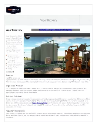
Vapor Recovery Units • Methane Losses • Methane Savings • Is Recovery Profitable? • Industry Experience • Lessons Learned
Sources of Methane Losses • A storage tank battery can vent 5,000 to 500,000 thousand cubic feet (Mcf) of natural gas and light hydrocarbon vapors to the atmosphere each year • Vapor losses are primarily a function of oil or condensate throughput, gravity, and gas-oil separator pressure • Flash losses • Occur when crude oil or condensate is transferred from a gas-oil separator at higher pressure to a storage tank at atmospheric pressure • Working losses • Occur when crude or condensate levels change and when liquid in tank is agitated • Standing losses • Occur with daily and seasonal temperature and barometric pressure changes
Methane Savings: Vapor Recovery • Vapor recovery can capture up to 95% of hydrocarbon vapors from tanks • Recovered vapors have higher heat content than pipeline quality natural gas • Recovered vapors are more valuable than natural gas and have multiple uses • Re-inject into sales pipeline • Use as on-site fuel • Send to processing plants for recovering valuable natural gas liquids
Types of Vapor Recovery Units • Conventional vapor recovery units (VRUs) • Use screw or vane compressor to suck vapors out of atmospheric pressure storage tanks • Scroll compressors are new to this market • Require electrical power or engine driver • Venturi ejector vapor recovery units (EVRUTM) or Vapor Jet • Use Venturi jet ejectors in place of rotary compressors • Contain no moving parts • EVRUTM requires a source of high pressure motive gas and intermediate pressure discharge system • Vapor Jet requires a high pressure water motive
Vent Line Back Pressure Valve Source: Evans & Nelson (1968) Control Pilot Suction Line Crude Oil Stock Tank(s) Electric Control Panel Suction Scrubber Bypass Valve Gas Gas Sales Meter Run Check Valve Liquid Transfer Pump Electric Driven Rotary Compressor Condensate Return Sales Conventional Vapor Recovery Unit
Pressure Indicator Temperature Indicator PI TI PI TI High-Pressure Motive Gas (~850 psig) Discharge Gas (~40 psia) TI Flow Safety Valve Suction Pressure (-0.05 to 0 psig) PI Low-Pressure Vent Gas from Tanks (0.10 to 0.30 psig) *EVRUTM Patented by COMM Engineering Adapted from SRI/USEPA-GHG-VR-19 psig = pound per square inch, gauge psia = pounds per square inch, absolute Venturi Jet Ejector*
Gas to Sales @ 1000 psig Compressor 6,200 Mcf/day 281 Mcf/day Net Recovery Gas (19 Mcf/day incremental fuel) 5,000 Mcf/day Gas 5,000 barrels/day Oil 900 Mcf/day Ejector 40 psig LP Separator Ratio Motive / Vent = 3 = 900/300 300 Mcf/day Gas Oil Oil & Gas Well Crude Oil Stock Tank Oil to Sales Vapor Recovery with Ejector Mcf = Thousand cubic feet
Vapor Jet System* *Patented by Hy-Bon Engineering
Vapor Jet System* • Utilizes produced water in closed loop system to effect gas gathering from tanks • Small centrifugal pump forces water into Venturi jet, creating vacuum effect • Limited to gas volumes of 77 Mcf/day and discharge pressure of 40 psig *Patented by Hy-Bon Engineering
Criteria for Vapor Recovery Unit Locations • Steady source and sufficient quantity of losses • Crude oil stock tank • Flash tank, heater/treater, water skimmer vents • Gas pneumatic controllers and pumps • Dehydrator still vent • Pig trap vent • Outlet for recovered gas • Access to low pressure gas pipeline, compressor suction, or on-site fuel system • Tank batteries not subject to air regulations
Quantify Volume of Losses • Estimate losses from chart based on oil characteristics, pressure, and temperature at each location (± 50%) • Estimate emissions using the E&P Tank Model (± 20%) • Engineering Equations – Vasquez Beggs (± 20%) • Measure losses using recording manometer and well tester or ultrasonic meter over several cycles (± 5%) • This is the best approach for facility design
Estimated Volume of Tank Vapors 110 100 90 80 API Gravities 70 40° API and Over Vapor Vented from Tanks, cubic foot / barrel Gas/Oil Ratio 60 50 30° API to 39° API 40 Under 30° API 30 20 10 10 20 30 40 50 60 70 80 Pressure of Vessel Dumping to Tank (Psig) o API = API gravity
Estimated Volume of Tank Vapors • Atmospheric tanks may emit large amounts of tank vapors at relatively low separator pressure Vasquez-Beggs Equation psig – pounds per square inch, gauge scf – standard cubic feet bbl – barrels
What is the Recovered Gas Worth? • Value depends on heat content of gas • Value depends on how gas is used • On-site fuel • Valued in terms of fuel that is replaced • Natural gas pipeline • Measured by the higher price for rich (higher heat content) gas • Gas processing plant • Measured by value of natural gas liquids and methane, which can be separated • Gross revenue per year = (Q x P x 365) + NGL • Q = Rate of vapor recovery (Mcf per day) • P = Price of natural gas • NGL = Value of natural gas liquids
Value of Natural Gas Liquids 1 – Natural Gas Price assumed at $7.15/MMBtu as on Mar 16, 2006 at Henry Hub2 – Prices of Individual NGL components are from Platts Oilgram for Mont Belvieu, TX July 11, 2008
Industry Experience: EnCana Oil & Gas • Vapor recovery unit installed in Frenchie Draw, WY • Captures vapors from • Separators • Crude oil storage tank • Non-condensable dehydrator still gas • VRU designed to handle 500 Mcf/day • Additional capacity over the estimated 284 Mcf/day of total gas from all emission sources
Industry Experience: EnCana Oil & Gas • Quantify the volume of vapor emissions Total Emissions- 284 MSCFD Source: EnCana Oil & Gas (USA) Inc.
EnCana Oil & Gas: Project Costs • Determine the cost of VRU project Installation VRU Unit (500 Mcfd) - $90,000 Generator- $85,000 Vent Header- $25,000 Labor- $200,000 TOTAL $400,000 O & M VRU Unit (500 Mcfd) - $15,000 Generator- $18,000 Fuel- $73,000 TOTAL $106,000
EnCana Oil & Gas: Project Economics • Evaluate VRU economics Capacity– 500 Mcfd Installation Cost - $400,000 O&M- $106,000/year Value of Gas*- $788,400/year Payback- 7 months Return on Investment- 170% *Gas price assumed to be $ 7.60 by Encana
Industry Experience: Anadarko • Vapor Recover Tower (VRT) • Add separation vessel between heater treater or low pressure separator and storage tanks that operates at or near atmospheric pressure • Operating pressure range: 1 psi to 5 psi • Compressor (VRU) is used to capture gas from VRT • Oil/Condensate gravity flows from VRT to storage tanks • VRT insulates the VRU from gas surges with stock tank level changes • VRT more tolerant to higher and lower pressures • Stable pressure allows better operating factor for VRU
Industry Experience: Anadarko • VRT reduces pressure drop from approximately 50 psig to 1-5 psig • Reduces flashing losses • Captures more product for sales • Anadarko netted between $7 to $8 million from 1993 to 1999 by utilizing VRT/VRU configuration • Equipment Capital Cost: $11,000 • Standard size VRTs available based on oil production rate • 20” x 35’ • 48” x 35’ • Anadarko has installed over 300 VRT/VRUs since 1993 and continues on an as needed basis
VRT/VRU Photos Courtesy of Anadarko
Lessons Learned • Vapor recovery can yield generous returns when there are market outlets for recovered gas • Recovered high heat content gas has extra value • Vapor recovery technology can be highly cost-effective in most general applications • Venturi jet models work well in certain niche applications, with reduced operating and maintenance costs • Potential for reduced compliance costs can be considered when evaluating economics of VRU, EVRUTM, or Vapor Jet
Lessons Learned (continued) • VRU should be sized for maximum volume expected from storage tanks (rule-of-thumb is to double daily average volume) • Rotary vane, screw or scroll type compressors recommended for VRUs where Venturi ejector jet designs are not applicable • EVRUTM recommended where there is a high pressure gas compressor with excess capacity • Vapor Jet recommended where there is produced water, less than 75 Mcf per day gas and discharge pressures below 40 psig
Methane Losses from Pipeline Pigging • Gas lost when launching and receiving a pig • Fugitive emissions from pig launcher/receiver valves • Gas lost from storage tanks receiving condensate removed by pigging • Gas vented from pipeline blowdowns
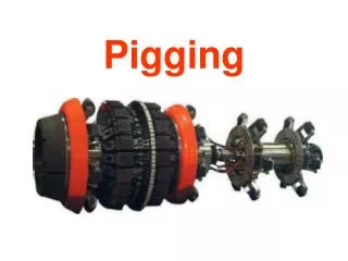
Pigging Pipelines • Hydrocarbons and water condense inside pipelines, causing pressure drop and reducing gas flow • Periodic line pigging removes liquids and debris to improve gas flow • Also inspect pipeline integrity • Efficient pigging: • Keeps pipeline running continuously • Keeps pipeline near maximum throughput by removing debris • Minimizes product losses during launch/capture Source: www.girardind.com/
Gas Flow Vent Valve Gas Flow Pig Launcher Source: www.girardind.com/ How Does Pigging Vent Methane? • Pig launchers have isolation valves for loading pigs, pressurizing pigs, and launching pigs with gas bypassed from the pipeline • Launcher pressuring/depressuring loses methane out the vent valve
Pigging Vents Methane Twice • Methane lost through vent valve on the launcher and again through vent valve on the receiver • Once receiver is isolated from the line, it must be depressured to remove the pig • Liquids ahead of the pig drain to a vessel or tank • MORE than twice:isolation valve leaks maycause excessive venting to depressure Source: www.girardind.com/
Methane Recovery • Pipeline maintenance requires pipe section blowdown before work can begin • Gas in pipeline is usually vented to the atmosphere • Use inert gasand pig • Route vent to vapor recovery system or fuel gas • One Partner reported connecting pig receiver vent to fuel gas to recover gas while working a tight isolation
Is Recovery Profitable? • One partner pigged gathering lines 30 to 40 times per year, collecting several thousand barrels of condensate per application • Partner reported saving 21,400 Mcf/year from recovering flash gases • Dedicated vapor recovery unit (VRU) was installed with an electric compressor at an installation cost of $24,000 and an annual operating cost of $40,000 mostly for electricity • Large gas savings and increasing gas prices will offset costs
Discussion • Industry experience applying these technologies and practices • Limitations on application of these technologies an practices • Actual costs and benefits