Download
1 / 24
240 likes | 399 Vues
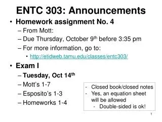
ENTC 303: Announcements. Homework assignment No. 4 From Mott : 6.36, 6.37, 6.61, 6.72, 6.78, 6.94, 7.3, 7.9, 7.17, 7.22, 7.23, 7.37. From Esposito : 3.59E and 3.62E. Due Thursday , October 9 th before 3:35 pm For more information, go to:

E N D
ENTC 303: Announcements • Homework assignment No. 4 • FromMott: 6.36, 6.37, 6.61, 6.72, 6.78, 6.94, 7.3, 7.9, 7.17, 7.22, 7.23, 7.37. • FromEsposito: 3.59E and 3.62E. • Due Thursday, October 9th before 3:35 pm • For more information, go to: • http://etidweb.tamu.edu/classes/entc303/ • Exam I • Tuesday, Oct 14th • Mott’s 1-7 • Esposito’s 1-3 • Homeworks 1-4 • Closed book/closed notes • Yes, an equation sheet will be allowed • Double-sided is ok!
Definitions • Volume (Volumetric) Flow Rate • Q = Cross Sectional Area*Average Velocity of the fluid • Q = A*v • Weight Flow Rate • W = g*Q • Mass Flow Rate • M = r*Q v Q = Volume/Unit time Q = Area*Distance/Unit Time Volume
Conservation of EnergyBernoulli’s Equation • Energy cannot be created or destroyed, just transformed • Three forms of energy in fluid system: • Potential • Kinetic • Flow energy
Potential Energy • Due to the elevation of the fluid element Where, w = weight of fluid element z = elevation with respect to a reference level
Kinetic Energy • Due to the velocity of the fluid element Where, v = average velocity of the fluid element
Flow Energy • Flow work or pressure energy • Amount of energy necessary to move a fluid element across a certain section against pressure Where, p = pressure on the fluid element
Flow Energy • Flow work or pressure energy • Amount of energy necessary to move a fluid element across a certain section against pressure
Total Energy and Conservation of Energy Principle • E = FE + PE + KE • Two points along the same pipe: E1 = E2 • Bernoulli’s Equation:
Heads Assumption: No energy is added or lost Assumption: Energy level remains constant
Restrictions on Bernoullis’ Equation • Valid only for incompressible fluids • No energy is added or removed by pumps, brakes, valves, etc. • No heat transfer from or to liquid • No energy lost due to friction Note: No system satisfies this condition, but Bernoulli’s equation can still be used to estimate changes in heads’ values
Application of Bernoulli’s Equation • Identify known and unknown items • Pick the end points of the system based on the data you have • Write Bernoulli’s equation in the direction of flow, left side of equation represents “from-side,” right side of equation represents “to-side” • Label diagram with appropriate subscripts • Simplify equation by canceling terms that are zero, or equal on both sides of the equation • Solve equation and find desired result(s)
A hose carries water at a flow rate of 0.01 m3/sec. The hose has an internal diameter of 12 mm, and the gauge pressure at faucet is 100 kPa. Determine the pressure at the end of the hose before water exits the hose. Example DZ = 10 m
Tanks, Reservoirs and Nozzles Exposed to the atmosphere • When a fluid is exposed to the atmosphere at both ends of the system, the gauge pressure is zero at both ends and the pressure head can be cancelled from the equation System 0 0 P=0 P 0 Location of P2 is just outside of pipe P =0
A B D-jet D-pipe E D C Tanks, Reservoirs and Nozzles Exposed to the atmosphere When a fluid is exposed to the atmosphere at both ends of the system, the gauge pressure is zero at both ends and the pressure head can be cancelled from the equation 0 0 Location of PE is just outside of pipe
Tanks, Reservoirs and Nozzles Exposed to the atmosphere • The velocity head at the surface of tank or reservoir is considered to be zero and it can be cancelled from the equation 0 0 0 System v = 0 V ≠ 0 V ≠ 0
Pipe or Canal at the same elevation • If two points of interest of a pipe of constant diameter are at the same elevation, the potential and velocity heads can be cancelled from the equation Same diameter Dz = 0 0 0 0 0
A B D-jet D-pipe E D C Pipe or Canal at the same elevation If two points of interest of a pipe of constant diameter are at the same elevation, the potential and velocity heads can be cancelled from the equation
Siphon, 40 mm in diameter, terminates with a 25 mm nozzle. Assuming there are no energy losses, calculate the flow rate and pressure at Points A, B, C, D and E. DzA-F = 3.0 M Example C 1.2 m A D B E F
For the venturi meter shown, determine the fluid velocity at A and the flowrate. The gage fluid’s SG is 1.25. Example 200 mm B 0.46 m A y 1.18 m 300 mm
A h B Torricelli’s Theorem • For a liquid flowing from a tank or reservoir with constant fluid elevation, the velocity through the orifice is given by: where, h is the difference in elevation between the orifice and the top of the tank
Flow Due to Falling Head A h(t) B Apply non-steady form of continuity equation
Torricelli’s Theorem • For a liquid flowing from a tank or reservoir with constant fluid elevation, the velocity through the orifice is given by: where, h is the difference in elevation between the orifice and the top of the tank Example: If h = 3.00 m, compute v2 h