Chapter Outline
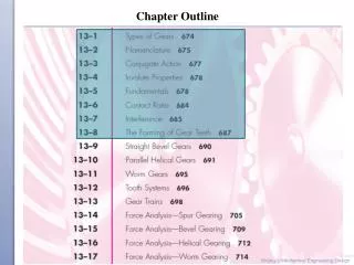
Chapter Outline. Types of Gears. Spur. Helical. Worm. Bevel. Figs. 13–1 to 13–4. Nomenclature of Spur-Gear Teeth. Fig. 13–5. Tooth Size. Tooth Sizes in General Use. Table 13–2. Standardized Tooth Systems (Spur Gears). Table 13–1. Standardized Tooth Systems.

Chapter Outline
E N D
Presentation Transcript
Chapter Outline Shigley’s Mechanical Engineering Design
Types of Gears Spur Helical Worm Bevel Figs. 13–1 to 13–4 Shigley’s Mechanical Engineering Design
Nomenclature of Spur-Gear Teeth Fig. 13–5 Shigley’s Mechanical Engineering Design
Tooth Size Shigley’s Mechanical Engineering Design
Tooth Sizes in General Use Table 13–2 Shigley’s Mechanical Engineering Design
Standardized Tooth Systems (Spur Gears) Table 13–1 Shigley’s Mechanical Engineering Design
Standardized Tooth Systems • Common pressure angle f: 20º and 25º • Old pressure angle: 14 ½º • Common face width: Shigley’s Mechanical Engineering Design
Conjugate Action • When surfaces roll/slide against each other and produce constant angular velocity ratio, they are said to have conjugate action. • Can be accomplished if instant center of velocity between the two bodies remains stationary between the grounded instant centers. Fig. 13–6 Shigley’s Mechanical Engineering Design
Conjugate Action • Forces are transmitted on line of action which is normal to the contacting surfaces. • Angular velocity ratio is inversely proportional to the radii to point P, the pitch point. • Circles drawn through P from each fixed pivot are pitch circles, each with a pitch radius. Fig. 13–6 Shigley’s Mechanical Engineering Design
Involute Profile • The most common conjugate profile is the involute profile. • Can be generated by unwrapping a string from a cylinder, keeping the string taut and tangent to the cylinder. • Circle is called base circle. Fig. 13–8 Shigley’s Mechanical Engineering Design
Involute Profile Producing Conjugate Action Fig. 13–7 Shigley’s Mechanical Engineering Design
Circles of a Gear Layout Fig. 13–9 Shigley’s Mechanical Engineering Design
Sequence of Gear Layout • Pitch circles in contact • Pressure line at desired pressure angle • Base circles tangent to pressure line • Involute profile from base circle • Cap teeth at addendum circle at 1/P from pitch circle • Root of teeth at dedendum circle at 1.25/P from pitch circle • Tooth spacing from circular pitch, p = p / P Fig. 13–9 Shigley’s Mechanical Engineering Design
Relation of Base Circle to Pressure Angle Fig. 13–10 Shigley’s Mechanical Engineering Design
Tooth Action • First point of contact at a where flank of pinion touches tip of gear • Last point of contact at b where tip of pinion touches flank of gear • Line ab is line of action • Angle of action is sum of angle of approach and angle of recess Fig. 13–12 Shigley’s Mechanical Engineering Design
Rack • A rack is a spur gear with an pitch diameter of infinity. • The sides of the teeth are straight lines making an angle to the line of centers equal to the pressure angle. • The base pitch and circular pitch, shown in Fig. 13–13, are related by Fig. 13–13 Shigley’s Mechanical Engineering Design
Internal Gear Fig. 13–14 Shigley’s Mechanical Engineering Design
Example 13–1 Shigley’s Mechanical Engineering Design
Example 13–1 Shigley’s Mechanical Engineering Design
Example 13–1 Shigley’s Mechanical Engineering Design
Contact Ratio • Arc of action qt is the sum of the arc of approach qa and the arc of recess qr., that is qt = qa + qr • The contact ratiomc is the ratio of the arc of action and the circular pitch. • The contact ratio is the average number of pairs of teeth in contact. Shigley’s Mechanical Engineering Design
Contact Ratio • Contact ratio can also be found from the length of the line of action • The contact ratio should be at least 1.2 Fig. 13–15 Shigley’s Mechanical Engineering Design
Interference • Contact of portions of tooth profiles that are not conjugate is called interference. • Occurs when contact occurs below the base circle • If teeth were produced by generating process (rather than stamping), then the generating process removes the interfering portion; known as undercutting. Fig. 13–16 Shigley’s Mechanical Engineering Design
Interference of Spur Gears • On spur and gear with one-to-one gear ratio, smallest number of teeth which will not have interference is • k =1 for full depth teeth. k = 0.8 for stub teeth • On spur meshed with larger gear with gear ratio mG = NG/NP = m, the smallest number of teeth which will not have interference is Shigley’s Mechanical Engineering Design
Interference of Spur Gears • Largest gear with a specified pinion that is interference-free is • Smallest spur pinion that is interference-free with a rack is Shigley’s Mechanical Engineering Design
Interference • For 20º pressure angle, the most useful values from Eqs. (13–11) and (13–12) are calculated and shown in the table below. Shigley’s Mechanical Engineering Design
Interference • Increasing the pressure angle to 25º allows smaller numbers of teeth Shigley’s Mechanical Engineering Design
Interference • Interference can be eliminated by using more teeth on the pinion. • However, if tooth size (that is diametral pitch P)is to be maintained, then an increase in teeth means an increase in diameter, since P = N/d. • Interference can also be eliminated by using a larger pressure angle. This results in a smaller base circle, so more of the tooth profile is involute. • This is the primary reason for larger pressure angle. • Note that the disadvantage of a larger pressure angle is an increase in radial force for the same amount of transmitted force. Shigley’s Mechanical Engineering Design
Forming of Gear Teeth • Common ways of forming gear teeth • Sand casting • Shell molding • Investment casting • Permanent-mold casting • Die casting • Centrifugal casting • Powder-metallurgy • Extrusion • Injection molding (for thermoplastics) • Cold forming Shigley’s Mechanical Engineering Design
Cutting of Gear Teeth • Common ways of cutting gear teeth • Milling • Shaping • Hobbing Shigley’s Mechanical Engineering Design
Shaping with Pinion Cutter Fig. 13–17 Shigley’s Mechanical Engineering Design
Shaping with a Rack Fig. 13–18 Shigley’s Mechanical Engineering Design
Hobbing a Worm Gear Fig. 13–19 Shigley’s Mechanical Engineering Design