Polarity inversion
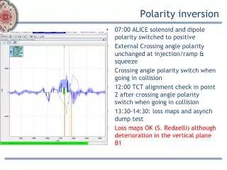
Polarity inversion. 07:00 ALICE solenoid and dipole polarity switched to positive External Crossing angle polarity unchanged at injection/ramp & squeeze Crossing angle polarity switch when going in collision

Polarity inversion
E N D
Presentation Transcript
Polarity inversion • 07:00 ALICE solenoid and dipole polarity switched to positive • External Crossing angle polarity unchanged at injection/ramp & squeeze • Crossing angle polarity switch when going in collision • 12:00 TCT alignment check in point 2 after crossing angle polarity switch when going in collision • 13:30-14:30: loss maps and asynch dump test • Loss maps OK (S. Redaelli) although deterioration in the vertical plane B1
Asynch dump test (J.Uythoven) • Dumped by OP switch 70 seconds after the RF OFF. Very little beam left for the asynch dump test. TCT losses are on the noise level. B1 TCT/TCDQ ratio < 2.2e-5 B2 TCT/TCDQ ratio < 3.5e-6 Abort gap population B1 3e8 charges and B2 1e9 charges, Did see abort gap populating when RF switched off. No significant losses at other places in the ring (from general PM). Asynch dump ok (JU).
RF status (P. Baudrenghien, T. Mastoridis) • Fill 2325 (Sat 26/11): • There were only 6 RF cavities during the fill in question. Unfortunately, the total RF voltage was not reduced sufficiently to accommodate the reduction of operating stations. So, each cavity was operating at 1.9 MV, thus leading to klystron saturation. • This saturation should not lead to drastic effects normally, so we cannot be positive that this is the source of the problem, but we are fairly certain. • We also don't see any indication that is related to the similar losses and debunching from last Sunday (Synchro Loop). • New RF voltage for B1 (now identical to B2): • capture with 8 MV, ramp to 12 MV as we (probably) will keep working with 7 cavities only in B1, I have changed the main coupler position from a QL=20 k to 25k to keep klystron power ~150kW with 7 cavities/8 MV total on B1. On beam 2 we have ~140 kW for 8 MV with 8 cavities at QL=20k. In physics all cavities at 60k, 12 MV/ring.
Tune feedback (R. Steinhagen) • Checked Tune-FB response for various bandwidth: for a reduction factor of five (0.2) the tune (step) perturbation is taken out after about 30 seconds (90% to 10%). Programmed bandwdith changes are linear (as by design). • Bandwidth reduction should reduce the maximum oscillation amplitude presently causing spurious QPS trips during the squeeze. • Following squeeze done with tune feedback (BW reduced by factor 5) ON in both planes no QPS trip and tune under control BW: 1 0.5 0.2 0.1
18:56 start collision and crossing angle polarity switch • 19:11 Stable Beams #2332. Initial luminosity 5.1x1026 cm-2s-1 • 20:23 Beam dump due to RF trip (PLC problem). End of fill #2332. 1.9 ub-1 after 1.2 h
Cryo problem • At 20:26 water level sensor of the cooling tower SF4 at pt 4 had a short-circuit, which resulted in an electrical shutdown of the tower (24V). This cut the water to the cryo and at 20:29 the cryo installation at pt 4 switched off. • Loss of insulation vacuum on DSLC being investigated • Recovery of cryo conditions not expected before 21:00 tonight. • He release through the RF He release valves ODH alarm • 22:45 Trip of Sector 81 • 23:10 Access for Firemen intervention to reset ODH alarm and verification • 00:30 Access for cryo in point 4 and in point 3
The door at P3 (PZ33) is broken and needs repair. The access team is preparing, and should start the repair at 8:30. First estimate is that this work will take 8 hrs • After the door is fixed. a patrol of pt 3 will be needed, asthe PZ33 is forced. • Until the repair of PZ33 door starts, a CSA Guardian is stationed at PZ33 to control access
Plans • Access during day and implementation of new BLMs fir aperture investigations left of Point 2 • Physics in the evening • Wedensday: VdM scan and physics over night • Thursday: ADT tuning and verification tests + Physics • ~1 hour end-of-fill study to measure damping time at top energy • Loss maps at injection using ADT (MD preparation) (max 1 h) • “gating off” the ADT for the first batch injected for tune measurement (parasitic • Friday: Aperture scan in point 2 at 3.5 TeV squeezed (<1 shift) during day then physics • Physics during WE • Quench MD Monday 5.12