Cardiovascular Principles
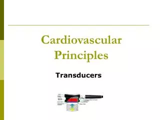
Cardiovascular Principles. Transducers. Definition. Ultrasound transducers are designed to convert electrical energy into mechanical energy and to convert ultrasound energy into electrical signals. Piezoelectricity. The piezoelectric effect is the formation of an electrical charge

Cardiovascular Principles
E N D
Presentation Transcript
Cardiovascular Principles Transducers
Definition Ultrasound transducers are designed to convert electrical energy into mechanical energy and to convert ultrasound energy into electrical signals.
Piezoelectricity The piezoelectric effect is the formation of an electrical charge on the surfaces of the crystal when pressure is applied.
Piezoelectricity Converse Piezoelectric Effect The converse piezoelectric effect is the change in the shape of the crystal when an electrical current is applied to the crystal.
Polarization Crystals made of Dipoles Dipoles are oblong asymmetric molecules that appear to have a positive charge at one end ant a negative charge at the other end. In non-polarized crystals these dipoles are disposed randomly.
Dipoles - + - + + - + - - + - + + + - + - -
Polarization • Process of geometrically aligning the dipoles of • of a crystal in order to give it piezoelectric • properties. • Steps • Formation and shaping of the crystal • Heat the crystal at very high temperature • Apply an electrostatic field • Lower the temperature with the electrostatic field applied
Dipoles + + + - - - + + + - - - + + + - - -
Curie Temperature The temperature at which polarization in a crystal is lost.
Resonance Frequency The frequency to which the ultrasound transducer is designed to be maximally sensitive both in its sending and receiving modes of operation
Resonance Frequency The thickness of the crystal determines the Resonance frequency. Ideal crystal thickness = ½ wavelength
Transducer • Piezoelectric crystal • Damping Block • Insulation ring • Tuning coil • Electric Shield • Electric Connectors • Housing
Transducer Electric Connector Housing Electric Shield Insulation Ring Electric Connector Matching Layer Damping Block Piezoelectric Crystal Tuning Coil
Unfocussed Transducer Transition Point 2NFL X Far Field 2X ½ X Near Field NFL
Unfocussed Transducer Near field = Near Zone = Fresnel Zone Far Field = Far Zone = Fraunhofer Zone NFL = ( trx. Diameter) 2 4 x wavelength
Unfocussed Transducer NFL = ( trx. Diameter) 2 4 x wavelength Increasing the frequency decreases the wavelength Increases the NFL
Transducer Central Beam Axis Side Lobes
Focused Transducer Focal Distance Focal Zone
Focusing • Mechanical • Internal • b. External
Focusing • DEFINITION: Narrowing of the beam • Mechanical • Internal • External • Electronic
Mechanically Focused Transducer Crystal Focusing Lens Focal Zone
Electronically Focused Transducer Electronic Delay
Spatial Resolution The ability of the transducer and the ultrasound system to resolve reflectors
Spatial Resolution • Axial • Lateral • Elevational
Spatial Resolution Axial Resolution = SPL / 2 Lateral Resolution = Beam width Elevational Resolution = Slice Thickness
Spatial Resolution Lateral Axial Elevational
Spatial Resolution Elevational Resolution Lateral Resolution
Frequency BandwidthSpectrum Analyzer Peak Amplitude Relative Amplitude -6 dB amplitude 2.5 5.0 7.5 Frequency mHz Frequency Bandwidth
Frequency Bandwidth • The range of frequencies contained in a pulsed wave • Factors • Imperfections in the crystal • Non parallel faces • Coupling of waves • Length of the excitation voltage
Transducer Frequency and Beam Shape Soft tissue attenuation modifies the frequency spectrum since higher frequencies in the pulse are attenuated to a greater degree than are the lower frequencies.
Beam Softening % 100 5.0 mHz Beam Remaining 7.5 mHz 10 mHz 0 2 4 6 Tissue Depth
Beam Softening The gradual loss of the higher frequency components of the sound beam is referred to as BEAM SOFTENING
Beam Softening Skin Surface Relative Amplitude 6 cm Depth 0 10 mHz
Beam Softening • As the sound wave travels in the tissue there • There is loss of amplitude • Beam softening • Narrower frequency bandwidth • Shift of the bandwidth to the left
Transducer Quality factor • Depends on • The purity of the ultrasound generated • The length of time that the ultrasound persists. • Q- factor = resonance frequency • frequency bandwidth
Q- Factor A. High Q B. Low Q Time
Q- Factor A. High Q Time Narrow Frequency Bandwidth
Q- Factor B. Low Q Time Wide Frequency Bandwidth
Frequency Bandwidth Relative Amplitude Curve Y Curve X 0.5 Curve X Curve Y 2.5 4.0 5.0 6.0 7.5
Matching Layer • Acoustic Impedance Mismatch • Reduce the magnitude of the mismatch • Add a Matching layer
Matching Layer Electric Connector Housing Electric Shield Insulation Ring Electric Connector No Matching Layer Damping Block Piezoelectric Crystal Tuning Coil
Matching Layer Housing Electric Shield Electric Connector Insulation Ring Electric Connector Single Matching Layer Damping Block Piezoelectric Crystal Tuning Coil
Matching Layer Thickness = ¼ wavelength Impedance = Square root of [Z(C) x Z(L)] Z(C) = Acoustic Impedance of the Crystal Z(L) = Acoustic Impedance of the Layer
Matching Layer Without Matching Layer Relative Amplitude With Single Matching Layer Frequency
Multiple Matching Layer • Computer models used to predict • optimum matching layer impedance • values. • This result in a stepwise transition of • impedances from crystal to tissue. • This leads to a further reduction of • acoustic mismatch and therefore a • decreased in Internal reflection. • The result is increased transmission • over a broader frequency band.
Matching Layer Single Matching layer – works well only for the center or resonance frequency. All other frequencies will be reflected to a greater or lesser extent. This results in a narrow frequency bandwidth.
Matching Layer • Broad-Banded Pulse Mean • Shorter SPL – Better axial resolution • Allows more latitude for electric tuning
Matching Layer Housing Electric Shield Electric Connector Insulation Ring Electric Connector Multiple Matching Layer Damping Block Piezoelectric Crystal Tuning Coil