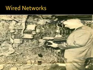
Wired LAN
Wired LAN. NET 352. Lecture Contents. LAN applications LAN topologies LAN media Internetworking LANs Bridges Hubs Switches Routers. LAN Applications. LAN Applications (1). personal computer LANs low cost limited data rate back end networks


Wired LAN
E N D
Presentation Transcript
Wired LAN NET 352 Networks and Communication Department
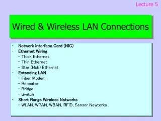
Lecture Contents • LAN applications • LAN topologies • LAN media • Internetworking LANs • Bridges • Hubs • Switches • Routers Networks and Communication Department
LAN Applications Networks and Communication Department
LAN Applications (1) • personal computer LANs • low cost • limited data rate • back end networks • interconnecting large systems (mainframes and large storage devices) • high data rate • high speed interface • distributed access • limited distance • limited number of devices
LAN Applications (2) • storage area networks (SANs) • DEF : separate network to handling storage needs • detaches storage tasks from specific servers • shared storage facility • eg. hard disks, tape libraries, CD arrays • accessed using a high-speed network • eg. Fibre Channel • improved client-server storage access • direct storage to storage communication for backup
LAN Applications (3) • high speed office networks • desktop image processing • high capacity local storage • backbone LANs • interconnect low speed local LANs • reliability • capacity • cost
LAN Topologies Networks and Communication Department
Bus and Tree • used with multipoint medium • transmission propagates throughout medium • heard by all stations • full duplex connection between station and tap • allows for transmission and reception • need to regulate transmission • to avoid collisions and hogging • terminatorabsorbs frames at end of medium • tree a generalization of bus • headend connected to branching cables
Ring Topology • a closed loop of repeaters joined by point to point links • receive data on one link & retransmit on another • links unidirectional • stations attach to repeaters • data in frames • circulate past all stations • destination recognizes address and copies frame • frame circulates back to source where it is removed • media access control determines when a station can insert frame
Star Topology • each station connects to central node • usually via two point to point links • either central node can broadcast • physical star, logical bus • only one station can transmit at a time • or central node can act as frame switch
Choice of Topology • reliability • expandability • performance • needs considering in context of: • medium • wiring layout • access control
LAN Media Networks and Communication Department
Bus LAN Transmission Media (1) • twisted pair • early LANs used voice grade cable • didn’t scale for fast LANs • not used in bus LANs now • baseband coaxial cable • uses digital signalling • original Ethernet
Bus LAN Transmission Media (2) • broadband coaxial cable • as in cable TV systems • analog signals at radio frequencies • expensive, hard to install and maintain • no longer used in LANs • optical fiber • expensive taps • better alternatives available • not used in bus LANs • less convenient compared to star topology twisted pair • coaxial baseband still used but not often in new installations
Ring and Star Usage • ring • very high speed links over long distances • single link or repeater failure disables network • star • uses natural layout of wiring in building • best for short distances • high data rates for small number of devices
Choice of Medium • constrained by LAN topology • capacity • reliability • types of data supported • environmental scope
Media Available • Voice grade unshielded twisted pair (UTP) • Cat 3 phone, cheap, low data rates • Shielded twisted pair / baseband coaxial • more expensive, higher data rates • Broadband cable • even more expensive, higher data rate • High performance UTP • Cat 5+, very high data rates, switched star topology • Optical fibre • security, high capacity, small size, high cost
Internetworking LANs Networks and Communication Department
Bridges • connects similar LANs • identical physical / link layer protocols • minimal processing • can map between MAC formats • reasons for use • reliability • performance • security • geography
Bridge Design Aspects • no modification to frame content or format • no encapsulation • exact bitwise copy of frame • minimal buffering to meet peak demand • contains routing and address intelligence • may connect more than two LANs • bridging is transparent to stations
Fixed Routing • complex large LANs need alternative routes • for load balancing and fault tolerance • bridge must decide whether to forward frame • bridge must decide LAN to forward frame to • can use fixed routing for each source-destination pair of LANs • done in configuration • usually least hop route • only changed when topology changes • widely used but limited flexibility
Spanning Tree • bridge automatically develops routing table • automatically updates routing table in response to changes • three mechanisms: • frame forwarding • address learning • loop resolution
Frame Forwarding • maintain forwarding database for each port • lists station addresses reached through each port • for a frame arriving on port X: • search forwarding database to see if MAC address is listed for any port except X • if address not found, forward to all ports except X • if address listed for port Y, check port Y for blocking or forwarding state • if not blocked, transmit frame through port Y
Address Learning • can preload forwarding database • when frame arrives at port X, it has come form the LAN attached to port X • use source address to update forwarding database for port X to include that address • have a timer on each entry in database • if timer expires, entry is removed • each time frame arrives, source address checked against forwarding database • if present timer is reset and direction recorded • if not present entry is created and timer set
Hubs • active central element of star layout • each station connected to hub by two UTP lines • hub acts as a repeater • limited to about 100 m by UTP properties • optical fiber may be used out to 500m • physically star, logically bus • transmission from a station seen by all others • if two stations transmit at the same time have a collision
Buses, Hubs and Switches • bus configuration • all stations share capacity of bus (e.g. 10Mbps) • only one station transmitting at a time • hubuses star wiring to attach stations • transmission from any station received by hub and retransmitted on all outgoing lines • only one station can transmit at a time • total capacity of LAN is 10 Mbps • can improve performance using a layer 2 switch • can switch multiple frames between separate ports • multiplying capacity of LAN
Layer 2 Switch Benefits • no changeto attached devices to convert bus LAN or hub LAN to switched LAN • e.g. Ethernet LANs use Ethernet MAC protocol • have dedicated capacity equal to original LAN • assuming switch has sufficient capacity to keep up with all devices • scales easily • additional devices attached to switch by increasing capacity of layer 2
Types of Layer 2 Switch • store-and-forward switch • accepts frame on input line, buffers briefly, routes to destination port • see delay between sender and receiver • better integrity • cut-through switch • use destination address at beginning of frame • switch begins repeating frame onto output line as soon asdestination address recognized • highest possible throughput • risk of propagating bad frames
Layer 2 Switch vs Bridge • Layer 2 switch can be viewed as full-duplex hub • incorporates logic to function as multiport bridge • differences between switches & bridges: • bridge frame handling done in software • switchperforms frame forwarding in hardware • bridgeanalyzes and forwardsone frame at a time • switchcan handle multiple frames at a time • bridgeusesstore-and-forwardoperation • switchcan havecut-throughoperation • hence bridge have suffered commercially
Layer 2 Switch Problems • broadcast overload • users share common MAC broadcast address • broadcast frames are delivered to all devices connected by layer 2 switches and/or bridges • broadcast frames can create big overhead • broadcast storm from malfunctioning devices • lack of multiple links • limits performance & reliability
Router Problems • typically use subnetworks connected by routers • limits broadcasts to single subnet • supports multiple paths between subnet • routers do all IP-level processing in software • high-speed LANs and high-performance layer 2 switches pump millions of packets per second • software-based router only able to handle well under a million packets per second
Layer 3 Switches • Solution:layer 3 switches • implement packet-forwarding logic of router in hardware • two categories • packet by packet • flow based
Packet by Packet or Flow Based • packet by packet • operates like a traditional router • order of magnitude increase in performance compared to software-based router • flow-based switch • enhances performance by identifying flows of IP packets with same source and destination • by observing ongoing traffic or using a special flow label in packet header (IPv6) • a predefined route is used for identified flows
Reference • Chapter 15 Networks and Communication Department