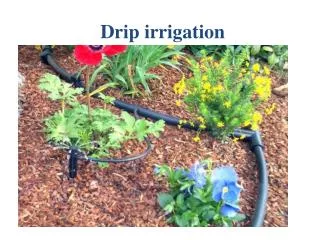
Drip Irrigation System Layout Design
ADVANTAGES. Water savingsCrop responseLabour savingsFertilizer savingsLess weed growth. Drip Irrigation System Layout


Drip Irrigation System Layout Design
E N D
Presentation Transcript
1. Drip Irrigation System Layout & Design
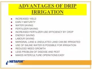
2. ADVANTAGES Water savings
Crop response
Labour savings
Fertilizer savings
Less weed growth
3. Saving in pesticides
Possible use of saline water
Early maturation
Minimum soil crusting
Field edge loss reduction ADVANTAGES
4. Improved root penetration
Irrigation of low intake soils
Easy field operation
ADVANTAGES
5. LIMITATIONS Sensitivity to clogging
Salinity hazards
Moisture distribution problems
High initial cost
Dry soil & dust formation
6. High skill required for
Design
Installation
Operation
Maintenance
LIMITATIONS
7. SYSTEM COMPONENTS Selection criteria
General suitability
Pressure flow characteristics
Manufacturing variability
8. Sensitivity to temperature
Resistance to clogging
Cost
Risk
SYSTEM COMPONENTS
9. Types
- Orifice emitter
q = C A
- Tube emitter
q = 0.034 h.78
- Labyrinth emitter
q = 0.125 h.78
SYSTEM COMPONENTS
11. SYSTEM COMPONENTS (Contd.) Lateral lines
Sub � mains
Main lines
Mani � folds
Filters
12. PROBLEMS IN FILTRATION Physical contamination
Chemical contamination
Effect of water source
Fitness of filtration
13. FILTERING EQUIPMENT & METHODS Pressure regulators
Control valves
Misc. fittings
17. DESIGN Amount of water to apply
q = C U . A. sc
qm =
Where :
qm is av. Emitter discharge in lph
H is total hr. of operation/day
N is nos. of emitters/ plant
q = C U . SI . Sm. sc
18. Spacing of emitters
Radius of coverage
R =
Max. spacing Sl X Sm
DESIGN
19. Uniformity of water distribution
Flow variation < 20%
Pressure variation < 20% DESIGN
20. Lateral & mainlines
Hazen William iq.
H = 15.25 X L
H = 5.35
(In decreasing flow lines)
DESIGN
21. DESIGN CHARTS Lateral for uniform slopes
Lateral for non-uniform slopes
Sub-main
Main
22. Example 1 GIVEN :
L = 50 m
H = 10 m
S = 1%
Emitter spacing = 0.3 m
q = 4 lph / emitter
23. FIND: Lateral dia.
L/H = 5
Q = 4 X 150 = 600 lph
= 0.167 lps
FIG. 6 (a)
12 mm is acceptable Example 1
24. Example 2 GIVEN:
L = 120 m Dia = 16 mm
H = 10 m Q = 0.13 lps
25. SLOPE:
0 � 30 3% down
30 � 60 2% down
60 � 90 0%
90 � 120 3% down Example 2
26. SOLUTION:
I/L HI (m) HI/ L
0.25 0.9 0.0075
0.5 1.5 0.0125
0.75 1.5 0.0125
1 2.4 0.02 Example 2
27. Plot I/L vs. HI/ L
OHP 12
H = 5.35 X L
=
Example 2
28.
= 1.5 m
= = .15
L/H = 120/10 = 12
Example 2
29. Check pressure variation at 4
points at I/L 0.25, 0.5, 0.75, 1. Fig 8
Variations are (QD III)
Less than 10%
Example 2
30. Example 3 GIVEN:
A= 20 ha Fig 11
Subplot = 0.4 ha
Q = 2 lps / subplot
31. Fig 12,
Plot mainline profile
Plot reqd. pressure head
Plot energy line
Use Fig 10 OHP 14 with S = 1 %
Find dia of mainline
Table 5 Example 3