Integrated Thruster Control
280 likes | 440 Vues
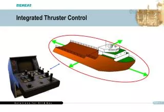
Integrated Thruster Control. Introduction. Integrated Thruster Control. The main objectives of the Thruster Control System is to actively control the thrust needed for position/heading of the vessel given by operator command or heading/positioning from an external Autopilot or DP system.

Integrated Thruster Control
E N D
Presentation Transcript
Introduction Integrated Thruster Control • The main objectives of the Thruster Control System is to actively control the thrust needed for position/heading of the vessel given by operator command or heading/positioning from an external Autopilot or DP system. • A vessel is subject to forces (process disturbance) from wind, waves and sea currents as well as own generated forces from the propulsion system. • Controlled thrust development by the vessel's thruster system counteracts these process disturbances created by wind, wave and sea current and enables the vessel to remain stationary relative to the sea bed position or to a defined course.
Introduction Integrated Thruster Control • The Thruster Control System is built around an advanced control algorithm. Vessel dynamics are computed to determine the theoretical thrust necessary to counteract forces created by thruster disturbances and a correction algorithm is built in for any deviation from desired vessel heading. • The Thruster Control System controls the vessel's motion in three degrees of freedom – surge, sway and yaw and is normally an integrated part of the overall control system. The Thruster Control System also includes a number of advanced maneuvering modes and functions and includes interface to various sensors, such as gyro, DGPS and environmental sensor(s).
Integrated Thruster Control • INTRODUCTION • The Siemens Thruster Control System contains the following functions: • Manual Lever Control • Joystick Control • Auto and Manual Heading Control • Wind/Wave and Current Compensation • Interface to Autopilot • Interface to - Integration of DP System (Up to Class 3) • Interface to Power Management System • Thruster and utilities primary equipment control • Sequencing - start and stop of thrusters and utilities • Emergency stop of thrusters/propulsion according to the class • Operational mode control • Command location control
Integrated Thruster Control • Basic Functionality - Manual Lever Control
Integrated Thruster Control • Manual Control from Thruster Console • Individual control of each thruster by manual levers • Tailor made levers to handle variants in the thruster installation: • Azimuth thruster control • Tunnel thruster control • Rudder and main propulsion control • Tailor made Thruster Console to present geographical wiev of the thruster/rudder installation on the vessel • Actual thruster position and propeller speed included on the thruster console to present true position and speed, in addition to presentation on display • Start and stop of individual thruster • Running, available and fault indication for each thruster • Emergency stop button for each thruster outside the control system • Thruster run-in mode included to reduce wear and tear during initial start-up and initial operation
Integrated Thruster Control • Joystick Control
Integrated Thruster Control • Joystick Control • Two operational modes: • Fixed azimuth mode • Free azimuth mode • Three possible rotation points • Three possible joystick gain settings • Up to 10 sectors for azimuth thruster positioning • Possibility for simultanous joystick and manual lever operation (option) • Auto heading control with maximum rotation speed limitation and with weather force compensation • Manual heading control • Manual positioning control • Fixed and portable joystick locations • Unlimited number of portable joystick operational positions
In fixed thruster mode the active thrusters will be fixed in predetermined directions, normally alongships and athwartships. The thrusters to be utilized alongships and athwartships are selected from the units activated for operation, based upon the magnitude and direction of prevailing weather forces. In this mode the thrusters may be turned 180 degrees to increase the maximum thrust in one direction by making available a forward thrust condition instead of a reversed thrust condition. The advantages of this control mode are: Minimisation of thruster wear Precise position keeping due to quick thruster response. This allocation mode is the most favorable in light weather conditions. Integrated Thruster Control • Joystick Control • Two operational modes fixed azimuth mode and free azimuth mode Fixed azimuth mode
Integrated Thruster Control • Joystick Control Free azimuth mode • The free thruster mode is optimal for rough weather conditions, and makes the total thrust capacity available by directing all thruster capacity in the direction of the resultant environmental force. The azimuth angle of the thrusters will be changed in parallel as the relative angle of the resulting force demand changes. The dynamic thrust variations, needed to keep the vessel in position, are obtained by the incremental change of rpm or azimuth for each individual thruster. • Various effects on thruster forces such as thruster-hull interaction and thruster-thruster interaction has been put into the allocation program and thus compensated for.
Integrated Thruster Control • Joystick Control - Heading Control • The system is capable of both automatic and manual heading control. • In automatic heading control, the set heading will be constantly maintained, also when the vessel is moved using the joystick. The system will compensate for weather conditions – waves, current and wind - in order to keep the heading. • In manual heading control, the yaw setpoint is set manually by the operator turning the joystick. The system will not compensate for weather condition
Integrated Thruster Control • Joystick Control - Rotational Speed Control • The maximum rotation speed in degrees/minute can be set by a system parameter. • A heading controller connected to a rotation speed controller will ensure precise heading control and limit the rotation speed.
Integrated Thruster Control • Joystick Control • 3 possible joystick gain settings Linear: linear relation between movement of the joystick and force exerted by the thrusters. The maximum force is a specified percentage of the achievable force from all thrusters. High:linear relation between movement of the joystick and force exerted by the thrusters. Increases the vessel's response to the movement of the joystick compared to the Normal selection. The maximum force available from all the thrusters can be used. Low:non-linear relation between movement of the joystick and force exerted by the thrusters. At small movements of the joystick the gain is low but increases with increasing movements.
Integrated Thruster Control • Joystick Control - Alternate Rotation Points • In the alternate rotation point mode the operator has the possibility to select 3 possible rotation points either the bow, center or stern. By using the yaw function on the joystick the vessel rotates around the point selected.
Integrated Thruster Control • Joystick Control - Interface to Autopilot/ECDIS • In autopilot control up to 4 azimuth thrusters or 2 rudders and 2 azimuth thrusters can be controlled by an autopilot. Normally for a vessel the two aft thrusters are controlled by the autopilot, while the remaining thrusters are controlled either by the manual levers or a combination of the manual levers/joystick. • The speed of the vessel is normally set by the joystick which in this mode controls the rpm/pitch for all thrusters while the azimuth for the two aft thrusters are controlled by the autopilot. • There exists also an option with autospeed functionality. A speed setpoint can be set on the screen and feedback is calculated based on data either from a speedlog or a DGPS. • The autopilot normally has a direct interface to an electronic chart (ECDIS) and a radar
Integrated Thruster Control • Joystick Control - Interface to - integration of higher class DP system • In DP mode the thruster set-points are calculated by the Dynamic Positioning Controller(s) and transferred to the Thruster Control System. Switching between the various modes is taken care of in the Thruster Control System as well as switching between setpoints from the various DP controllers in case of class 3 DP control. Necessary feedbacks from the thrusters and power system are transferred to the DP system constantly regardless of the mode selected.
Integrated Thruster Control • Basic Functionality - Wind Compensation • Wind compensation is based on calculation of surge, sway and yaw components derived from sensor data and vessel model. Gust Wind 4-20 mA Wind force calculation: based on: - Gust wind speed - Gust wind direction - 1 min. mean wind speed - 1 min. mean wind direct. Average Wind Serial Line
Integrated Thruster Control • Extended Functionality - Current/Wave Compensation • Wave and current compensation is based on calculation of surge, sway and yaw components derived from sensor data and vessel model. Wave and current force calculation based on: - Significant wave height - Primary wave peak period - Primary wave peak direction - Mean zero up crossing period - Surface current magnitude - Surface current direction Interface to Wave Radar
Integrated Thruster Control • Extended Functionality - Draught Compensation • The calculation of wind, wave and current forces are adjusted for variations in the vessel draught.
Integrated Thruster Control • Forbidden Sector Adjustment (in all modes except DP) • During normal use of the thruster forbidden sector settings can be defined. Up to 10 forbidden sectors can be defined each consisting of a start angle and an end angle. If a thruster is operated in the forbidden sector area the output azimuth will be adjusted to the allowable azimuth nearest the actual setting as shown in the figure.
Integrated Thruster Control • Thruster Run-In Service (in manual lever mode) • Selected Thrusters may be set in thruster Run-inservice in which they will be loaded less than their nominal rating. The maximum running-in torque can be specified to a percentage of nominal torque. This service is intended to reduce the wear on new thrusters whilst being running in.
Integrated Thruster Control • Tailor made thruster console
Integrated Thruster Control • Tailor made thruster console • Emergency Stop Arrangement according to thruster/propulsion layout • Mode Selection including DP system (also class 3) • Command Transfer according to actual installation • Lever Section according to thruster/propulsion layout. • Operator console layout is important by knowing that 85% of drive-off/drift-off is caused by human errors.
Intgegrated with Power Management System Integrated Thruster Control
Thruster Control on Stena Don • Interface to thruster drives (Variable Speed Drive) • The interface between the variable speed drive and the thruster control has been simplified by using fieldbus technology (Profibus DP). This ensures better utilisation of the drive. Drive Controller Simadyn D Thruster Controller Simatic S7-417 Profibus DP
Siemens Scope of Supply - Stena Don • Supervisory computer including joystick control • Variable speed drives (Simovert MV) for Thrusters • Thruster Drive motors • Motor Control Centre including intelligent motorstarter Simocode • AC 690V motors for hydraulic pumps and lube oil pumps • Thruster console • Simatic for local thruster control • Speedlog • Gyro • Autopilot • Electronic chart system • Position reference system • EMS computer system including wave radar • DP system class 3 (third party)
Thruster Control • Why Siemens Thruster Control: • Integrates all systems needed for propulsion/positioning of a ship regardless of who is the equipment supplier. • Takes care of all class related aspects related to operation of the propulsion/positioning system (mode selection, emergency stop, command transfer) • Advanced joystick control which is classed as a DP system - Class-0. • Joystick control is based on optimum control - saves fuel. • Uses field bus technology which saves cabling and installation work • Extensive use of remote I/O which saves space and weight on board a ship. Remote I/O ensures high flexibility in the design - saves cost. Cabinet boxes can be mounted close to the thrusters (field equipment). IP rating is IP 66 as standard. • High flexibility in the design • Integrates the drive in an efficient manner with better utilisation of the drive (torque, power control - overdrive functionality). • Can easily be integrated with other parts of the Siemens Control System for vessels.