Download

1 / 18
180 likes | 383 Vues
Data Communication and Networking. 332 Hardware Components of Data Communication. Lecture Overview. Signal Modulation AM FM PM QPSK QPM. Signal Modulation. The process of varying the electrical energy is modulation .

E N D
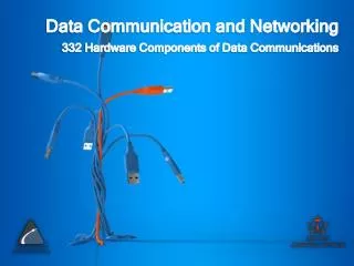
Data Communication and Networking 332 Hardware Components of Data Communication
Lecture Overview • Signal Modulation • AM • FM • PM • QPSK • QPM
Signal Modulation • The process of varying the electrical energy is modulation. • The high amplitude, high frequency, and fixed frequency level of energy that flows through the channel is the signal carrier. • An electronic device varies this carrier to reflect the information contained in a weaker voice or data signal. • Original computer and telephone signals often lack the strength to go far enough to be useful. • A modulation device can generate a combined signal strong enough to make it to its destination • Another device called a demodulatorhas to separate the signal that arrives at its destination
Analog Signal Modulation • The three primary analog techniques are • amplitude modulation, frequency modulation, and phase modulation. • A matching demodulation technique requires on the receiving end of the link
Amplitude Modulation • First used this technique for radio broadcast. • Easy to implement on the transmitting end, and the demodulation was easy and Inexpensive on the receiving end. • Constant frequency but varies in amplitude over time to convey information. • Lower-frequency information signal is imposed on the carrier • The amplitude of the resulting compound signal varies within an envelope that matches the form of the signal
Amplitude Modulation • Disadvantage • Any noise can adversely affect the demodulation of the AM signal. • Electrical noise can result in misinterpretation of the signal • Amplifiers amplify both the signal and the noise that has contaminated the signal.
Amplitude Modulation Amplitude modulation signal generation
Frequency Modulation • Has a constant amplitude but varies in frequency over time to convey information. • Imposing the lower-frequency information signal on the carrier • The frequency of the resulting compound signal varies to match the form of the information signal. • The disadvantage of FM is the bandwidth it takes to transmit a signal has a wider spectrum being wider in bandwidth the number of FM signals transmitted through a medium is smaller than the number of AM signals. • Low-speed modems use FM technique to convert digital signals into FM signals. • This process of frequency shift keying (FSK)
Frequency Modulation Frequency modulation signal generation and FM signal bandwidth
Phase Modulation • This technique does not apply widely to radio communications, • Vendors use the technique to convey color information in color television broadcasts. • PM a better alternative to AM and FM techniques. • More difficult to understand than AM and FM • Allows computers to communicate at high data rates through the telephone system. • Requires at least two analog signals. • The first signal is the carrier; all other signals modify the carrier signal to convey information.
Phase Modulation • Imposes information on the carrier by changing the shape of the carrier’s signal curve at a given points in time. • Signal cross the amplitude reference line at different times and are therefore different in phase. • The different in phase between two sine waves is phase angle, from 0 to 360 • The break point is the phase change that conveys the information for the compound signal. • A reference pattern allows designers to design and build PM circuits. • Can build a circuit that locks onto a carrier’s frequency to eliminates it to leave the information signal.
Phase Modulation Carrier and information signals 180 degrees different in phase, and a phase modulated signal.
Quadrature Phase Shift Keying • QPSK (Quadrature Phase Shift Keying): • 2 bits coded as one symbol • symbol determines shift of sine wave • needs less bandwidth • more complex • Transmitter and receiver are synchronized very often. • Each represents two bits: • 45 degree phase shift = 11; • 135 degree phase shift = 10; • 225 degree phase shift = 01; • 315 degree phase shift = 00.
Quadrature Phase Shift Keying Four phase angles of 45, 135, 225, and 315 degrees.
Quadrature Phase Modulation • Quadrature Amplitude Modulation (QAM): combines amplitude and phase modulation • In a QAM signal, there are two carriers, each having the same frequency but differing in phase by 90 degrees (one quarter of a cycle, from which the term quadrature arises) • The two modulated carriers are combined at the source for transmission. At the destination, the carriers are separated, the data is extracted from each, and then the data is combined into the original modulating information.
Quadrature Phase Modulation • Advantage: • Increase the efficiency of transmission for radio communications systems by utilizing both amplitude and phase variations • Disadvantage: • It is more susceptible to noise because the states are closer together so that a lower level of noise is needed to move the signal to a different decision point.