Download
1 / 29
290 likes | 309 Vues
This presentation discusses the design of a vertical KO vessel without internals for efficient separation of liquid droplets in the vapor stream, considering liquid retention time and pressure vessel economics. It includes step-by-step calculations and considerations for vapor and liquid dynamics.

E N D
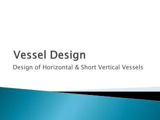
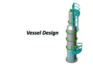
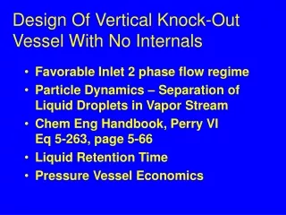
Design Of Vertical Knock-Out Vessel With No Internals • Favorable Inlet 2 phase flow regime • Particle Dynamics – Separation of Liquid Droplets in Vapor Stream • Chem Eng Handbook, Perry VIEq 5-263, page 5-66 • Liquid Retention Time • Pressure Vessel Economics
Types of Vertical KO Vessels • Vertical – No Internals • Vertical – With Demister Mesh • Peerless - In-line or Vari-line Vanes • Peerless Vane Type Line Separator • FWG – Vertical Flow Chevron Vanes • Cyclone With Tangential Inlet Entry • Porta-Test Centripetal Flow Type
Types Of Horizontal KO Pots • API-521 Horizontal With No Internals • API-521 Horizontal With Mesh Pad • Wu – Horizontal With Extended Inlet • FWG – Horizontal Flow Chevron Type • Porta-Test Recycling Separator • Peerless Horizontal Gas Separator • Kettle Refrigeration Exchanger
This Presentation Considers • Vertical KO Vessel With No Internals • Vertical KO With Mesh Pad
Problem Statement • Design a KO Pot to separate 49,423 lb/hr of vapor from 382,290 lb/hr of liquid. • Working Range liquid level holdup shall be +/- 2 minutes on normal liquid level. • Provide 2 minutes liquid holdup from high opg LL to Max LL. • Provide 2 minutes liquid holdup from low opg LL to Min. LL. • Total Liquid Retention time = 8 minutes.
First Design Consideration • As the liquid rate is high (382,290 lb/hr), liquid volume will probably be the controlling design factor. • Consider using a Standard Vertical KO Pot with No Internals.
Problem Statement Cont’d • Vapor Destination – centrifugal compressor. • Liquid Destination – C2 Splitter reflux. • Compressor Spec – To prevent damage to the compressor, the liquid droplet size in the inlet vapor stream shall not exceed a particle diameter, Dp, of 150 to 300 microns. • Design Spec – To achieve a goal of 150 microns, design the KO Pot for a particle diameter, Dp = 100 microns (or smaller).
Step (1): Calc CFS Of Vapor • CFS = Vapor cubic feet per second. • CFS Vapor = Wv/3600/Dv. • CFS Vapor = 16.29 cubic ft. per sec.
Step (2): Calc ( C )( Re^2 ) • CRe^2 from Perry VI - Eq 5-263 • CRe^2 = (A)( Constant) • A = (Dp/304800)^3(DL - Dv)(Dv) / cP^2 • Constant = (4*32.2/3/0.00067197^2) • CRe^2 = 1,411.49 Where C = Drag Coefficient Re = Particle Reynolds Number
Step (3): Calc Drag Coefficient, C • Table 5-22, Perry VI, Page 5-67, gives C values versus CRe^2. These values have been curve fitted to a polynomial for the Re range 0.1 to 2,000 as follows: • C = EXP(6.496-1.1478*LN(CRe^2) +0.058065*LN(CRe^2)^2-0.00097081*LN(CRe^2)^3) • C = 2.35 for the example presented
Step (4): Calc Particle Reynolds Number, Re • Re = (CRe^2 / C)^0.5 • Re = 24.5 • Re falls within range 0.1 < Re < 2,000 OK to proceed to Step (5)
Step (5): Calc Drop Out Velocity • Drop Out velocity, ut, from Perry VI - Eq 5-264. • Ut = [Re / C*4*32.2*cP*0.00067197*(DL-Dv) / 3 / Dv^2]^0.333333. • Ut = 0.4659 ft./sec.
Step (6): Calc Vessel Diameter • Area = (CFS / ut) = (3.14 / 4 )(D)^2. • KO Dia = (CFS / ut /0.785)^0.5. • KO Dia = 6.67 ft. • Round Diameter to Nearest 3.” • Rounded Diameter = 7’ 0.”
Step (7): Calc Ht. Above C.L. Of Inlet Nozzle, L1 • L1 Vapor ht. Referenced to C.L. Of inlet nozzle. • L1 Vapor ht. = 3 ft. + 0.5(Noz Diam.). • L1 Vapor ht. = 3.83 ft. (C.L. to top t-L). • See Design Uncertainty at end of this report for future addition of a demister pad, if required.
Step (8): Calc Liquid Vol, L3, For Specified Retention Time • Cubic Ft. Of Liquid = Vol L3. • Vol L3 = (WL)(Ø min.) / DL / 60 cu. ft. • Vol L3 = 1,629.02 cu. Ft.
Step (9): Calc Liq Vol for minimum of 2 ft. Liquid. • Liq Vol For 2 Ft. Minimum Liq Vol = Vol L2 ft. = (p)(2)(Dia)^2 / 4. • Vol L2 ft. = 76.97 cu. Ft.
Step (10): Select Maximum of L3 Vol or L2 ft. Vol. • Vol L3 = 1,629.02 cu. Ft. • Vol L2 = 76.97 ft. cu. Ft. = cu. Ft. • Max Liquid Vol = 1,629.02 cu. Ft.
Step (11): calculate L3, ft. • L3 = (Vol L3)(4) / (p)(Vessel Dia)^2. • L3 = 42.33 ft. • This makes the vessel roughly 7 ft. in diam with an unusually high liquid level (L3).
Step (12): Document Liquid Retention Time • Stated Liquid Retention Time Required from Max to Min Liquid Level = 8 minutes.
Step (13): Calculate L2 • L2 is the height from the C.L. of the inlet nozzle to the max Liquid level. • L2 = 0.25(L3) + 0.5(Inlet Nozzle dia.). • L2 = (0.25)(42.33) + (0.5)(20/12) =11.42 ft.
Step (14): Calculate t-t Length • L total t-t = L1 + L2 + L3. • L total t-t = 3.83 + 11.42 + 42.33. • L total t-t = 57.58. • L/D = 57.58 / 6.67 = 8.63. • Economic L/D range between 3 to 4. • Repeat Process with lower Dp to increase dia and lower t-t length. • Second Pass. Try Dp = 50 microns.
Design Basis • Design is vapor liquid systems with lower liquid rates. • The particl size is usually set at a default value of 500 microns, which is rain drop sized particles. • The wire mesh demister pad is usually 6 to 12 inches thick. • The vapor stream will exit with liquid drops no greater than 3 microns.
Design Procedure • The design procedure is exactly the same as for KO Pots without internals. • Set the particle size at 500 microns and proceed as before till an economic vessel with and L/D range of 3 to 4 is found.
Design Uncertainty • If the design is based on a vertical vessel with no internals and there is some uncertainty that the KO Pot will achieve the desired liquid particle size, provision can be made to add a wire mesh demister pad at a later date.
Future Demister Pad • Make L1 a minimum of 3 ft. + 0.5(inlet nozzle dia.) for vessel diameters 4 ft. and smaller. • For vessels larger than 4 ft. in dia., make L 1 = 0.75(Vessel dia.). • This will allow room to add a demister at a later date, if needed.