Optical sources
Optical sources. Lecture 5. Introduction. Its fundamental function is to convert electrical energy in the form of a current into optical energy (light) in an efficient manner which allows the light output to be effectively launched or coupled into the optical fiber.

Optical sources
E N D
Presentation Transcript
Optical sources Lecture 5
Introduction Its fundamental function is to convert electrical energy in the form of a current into optical energy (light) in an efficient manner which allows the light output to be effectively launched or coupled into the optical fiber.
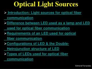
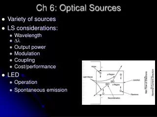
Three main types of optical light source • Wideband ‘continuos spectra’ sources (incandescent lamps); • Monochromatic incoherent sources (light-emitting diodes, LEDs); • Monochromatic coherent sources (lasers).
Major requirements for an optical fiber emitter • A size and configuration compatible with launching light into an optical fiber. • Ideally, the light output should be highly directional. The source should be linear (to track the electrical signal). • Should emit light at wavelengths where the fiber has low losses and low dispersion and where the detectors are efficient. • Must couple sufficient optical power to overcome attenuation in the fiber plus additional connector losses. • Should have a very narrow spectral bandwidth (linewidth) in order to minimize dispersion in the fiber. • Must be capable of maintaining a stable optical output which is largely unaffected by medium changes (e.g. temperature). • It is essential that the source is comparatively cheap and highly reliable.
Optical sources are classification • Optical sources are classified according to wavelength • Short wavelength sources (500-1000 nm, e.g. GaAlAs=Gallium Aluminum Arsenic) • Long wavelength sources (1200-1600 nm, e.g. InGaAsP= Indium Gallium Arsenic Phosphorus)
Basic concepts • (LASER): Light Amplification by Stimulated Emission of Radiation. Absorption and emission of radiation • The interaction of light with matter takes place in discrete packets of energy or quanta, called photons. • The frequency of the absorbed or emitted radiation f is related to the difference in energy E between the higher energy state E2 and the lower energy state E1 by the expression: E = E2 − E1 = hf where h = 6.626 × 10⁻³⁴ J s is Planck’s constant.
Basic concepts • Light can be generated by a radiative recombination of an electron and a hole within a semiconductor • Electron and hole may recombine non radiatively producing heat • The internal quantum efficiency • Optical sources use semiconductor material with high internal quantum efficiency
Absorption: When a photon with energy (E2 − E1) is incident on the atom it may be excited into the higher energy state E2 through absorption of the photon. • Spontaneous emission: in which the atom returns to the lower energy state in an entirely random manner, e.g. Light Emitting Diode (LED). • Stimulated emission: when a photon having an energy equal to the energy difference between the two states (E2 − E1) interacts with the atom in the upper energy state causing it to return to the lower state with the creation of a second photon, e.g. Semiconductor Laser Diode (SLD).
(a) absorption; (b) spontaneous emission; (c) stimulated emission.
The random nature of the spontaneous emission process where light is emitted by electronic transitions from a large number of atoms gives incoherent radiation. • A similar emission process in semiconductors provides the basic mechanism for light generation within the LED
Light amplification in the laser occurs when a photon colliding with an atom in the excited energy state causes the stimulated emission of a second photon and then both these photons release two more. • Continuation of this process effectively creates mass multiplication, and when the electromagnetic waves associated with these photons are in phase, amplified coherent emission is obtained. • To achieve this laser action it is necessary to contain photons within the laser medium and maintain the conditions for coherence. • This is accomplished by placing or forming mirrors (plane or curved) at either end of the amplifying medium
The basic laser structure incorporating plane mirrors The resonance condition along the axis of the cavity requires the optical spacing between the mirrors L to be where λ is the emission wavelength, n is the refractive index of the amplifying medium and q is an integer.
Alternatively, discrete emission frequencies f are defined by: where c is the velocity of light. These modes are separated by a frequency interval δfwhere:
The relative amplification in the laser amplifying medium showing the broadened laser transition line or gain curve.
(a) The modes in the laser cavity(b) The longitudinal modes in the laser
Transverse modes • Phase reversals produce the various mode patterns. Thus the greatest degree of coherence, together with the highest level of spectral purity, may be obtained from a laser which operates in only the TEM00 mode.
The lower order transverse modes of a laser • Higher order transverse modes only occur when the width of the cavity is sufficient for them to oscillate. Consequently, they may be eliminated by suitable narrowing of the laser cavity.
Light-Emitting Diodes • An LED is form of junction diode that is operated with forward bias. • Instead of generating heat at the PN junction, light is generated and passes through an opening or lens. • LEDs can be visible spectrum or infrared
LED configuration • Surface Emitting LED (SELED): used with MM fibers • n-type InP buffer layer 2-5µm thick • p-type InGaAsP active layer 0.4-1.5 µm thick • p-type InP layer 1-2 µm thick • p+-type InGaAs layer 0.2 µm thick • The light is emitted from circular planar region (20-50 µm) • The emitted beam of SELED is circularly symmetric with 60o typical half cone angle beam divergence
LED configuration • Edge Emitting LED (EELED): used with both SM and MM fibers. • EELED has elliptical beam pattern
LED configuration • EELED has active layer 0.05-0.25 µm
Laser Diodes • Laser diodes generate coherent, intense light of a very narrow bandwidth • A laser diode has an emission linewidth of about 2 nm, compared to 50 nm for a common LED • Laser diodes are constructed much like LEDs but operate at higher current levels