Download
1 / 14
140 likes | 293 Vues
Review of last lecture Generator polynomials Stop-and-wait, Go-back-N ARQ Today’s lecture Selective Repeat ARQ Analysis of all ARQ schemes Synchronous service HDLC and PPP Reading: Chaps 5.1-5.4. ELEN 602 Lecture 6. Timing Recovery. Synchronous source sends periodic information blocks.

E N D
Review of last lecture Generator polynomials Stop-and-wait, Go-back-N ARQ Today’s lecture Selective Repeat ARQ Analysis of all ARQ schemes Synchronous service HDLC and PPP Reading: Chaps 5.1-5.4 ELEN 602 Lecture 6
Timing Recovery Synchronous source sends periodic information blocks Network output not periodic Network
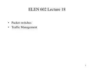
Impact of clock rate differences arrival times time send times Receiver too slow buffer overflow playout times Tplayout time Receiver speed just right Receiver too fast buffer starvation time time Many late packets time Tplayout Tplayout time
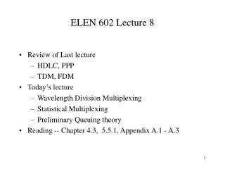
Adaptive Clock Recovery Buffer for information blocks Playout command Error signal + Adjust frequency Smoothing filter Add Recovered clock t3 t1 t4 t2 - Timestamps Counter
f f Clock Recovery with Synchronous Network Receiver Transmitter Network fs fr fn Network clock
The Data Link Layer NLPDU Network Layer Network Layer “packet” DLSAP DLSDU DLSDU DLSAP DLPDU Data Link Layer Data Link Layer “frame” Physical Layer Physical Layer
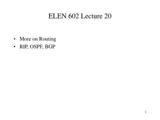
HDLC Configurations Unbalanced Point-to-point link Commands Primary Secondary Responses Unbalanced Multipoint link Commands Primary Responses Secondary Secondary Secondary Balanced Point-to-point link between Combined Stations Commands Secondary Primary Responses Primary Secondary Commands Responses
HDLC Frame Format Flag Address FCS Control Information Flag
Control Field Format Information Frame 1 5 2-4 6-8 N(R) 0 N(S) P/F Supervisory Frame 1 N(R) 0 S S P/F Unnumbered Frame 1 1 M M M M P/F M
Connection Establishment and Release Data transfer SABM UA UA DISC
Exchange of Frames -Normal Response Mode Secondaries B, C Primary A B, RR, 0, P B, I, 0, 0 B, I, 1, 0 X B, I, 2, 0,F B, SREJ, 1 C, RR, 0, P C, RR, 0, F B, SREJ, 1,P B, I, 1, 0 B, I, 3, 0 B, I, 4, 0, F B, I, 0, 5
Exchange of Frames - Asynchronous Balanced Mode Combined Station A Combined Station B B, I, 0, 0 A, I, 0, 0 B, I, 1, 0 A, I, 1, 1 X A, I, 2, 1 B, I, 2, 1 B, I, 3, 2 B, REJ, 1 B, I, 4, 3 A, I, 3, 1 B, I, 1, 3 B, I, 2, 4 B, RR, 2 B, I, 3, 4 B, RR, 3
PPP Frame Format flag Address Flag Control Protocol Information CRC 01111110 01111110 1111111 00000011 All stations are to accept the frame Specifies what kind of packet is contained in the payload, e.g., LCP, NCP, IP, OSI CLNP, IPX Unnumbered frame
Home PC to Internet Service Provider 1. PC calls router via modem. 2. PC and router exchange LCP packets to negotiate PPP parameters. 3. Check on identities. 4. NCP packets exchanged to configure the network layer, e.g., TCP/IP ( requires IP address assignment). 5. Data transport, e.g. send/receive IP packets. 6. NCP used to tear down the network layer connection (free up IP address); LCP used to shut down data link layer connection. 7. Modem hangs up. A Typical Scenario-- PPP Phase Diagram 1. Carrier Detected Dead 7. Carrier Dropped failed Establish Terminate 2. Options Negotiated 6. Done failed Authenticate 5. Open 3. Authentication Completed 4. NCP Configuration Network