Download
1 / 25
250 likes | 381 Vues
LHC Commissioning Phases. 450GeV Initial Commissioning presented by Rhodri Jones (AB/BI) on behalf of the LHCCWG Particular thanks to the A. Butterworth, B. Goddard, W. Hofle, V. Kain, R. Steinhagen & J. Wenninger. LHC Commissioning Phases: Phase 3 – 450GeV Initial Commissioning.

E N D
LHC Commissioning Phases 450GeV Initial Commissioning presented by Rhodri Jones (AB/BI) on behalf of the LHCCWG Particular thanks to the A. Butterworth, B. Goddard, W. Hofle, V. Kain, R. Steinhagen & J. Wenninger
LHC Commissioning Phases: Phase 3 – 450GeV Initial Commissioning • Phase A.3: 450GeV Initial Commissioning • Objectives • Entry conditions • Preconditions and tools • Commissioning procedure • Exit conditions • Summary
LHC Stage A: Commissioning phases Phases for full commissioning Stage A (pilot physics run) Basic Objectives: • Continued RF commissioning • Initial commissioning of beam dump • Commissioning of beam instrumentation • To reach a lifetime > 1hr at 450GeV
450GeV Initial Commissioning – Overview of Steps Involved • Steps 1 to 3 carried out with a single pilot bunch of 5×10⁹ • Remaining steps carried out with a single intermediate bunch of ~ 3×10¹⁰ • higher precision on measurements & easier for BI commissioning • All steps carried out first on one beam then on the other • same “experts” will be required for both systems
450GeV Initial Commissioning – entry conditions Beam Entry conditions: • RF Captured • Beam circulating for hundreds of turns (orbit, tune & chromaticity coarsely adjusted) Additional Hardware/Software Entry conditions: • Point 6, extraction channel • Dry runs and 450 GeV reliability run completed • Collimator control system • TCPs, TCDQ, TCSG and TDI moveable • Collimator movements for TCP, TCDQ, IR6 TCS, TDI hardware calibrated • Inject & dump / circulate & dump modes available • both scenarios hardware commissioned • timing tables available • RF synchronisation hardware tested and available • Additional RF Systems • Transverse damper available • Additional Beam Instrumentation • BCTDC hardware available • Interlock BPMs in LSS6 available • Tune meter & tune hardware PLL available • Tune kicker & tune tickler hardware available • Head-Tail monitor available • Wire Scanner available • Abort Gap Monitor (BSRA) available • Applications & controls • XPOC GUI and analysis package available in the control room • GUIs for all RF & BI instrumentation
450GeV Initial Commissioning – Stage A.3.1 – RF (Pilot) • Further RF commissioning • Details still to be presented at LHCCWG • will be put on the agenda for a future meeting • Transverse damper (some preliminary comments from W. Hofle) • As an exciter the damper system will be available from day 1 • The damper pick-up electronics can be commissioned as soon as there is circulating beam • Injection damping should only be attempted once • a stable tune has been established • the phase advance between the damper pick-ups is reasonably well known • These 2 conditions push this towards the end of this Stage
450GeV Initial Commissioning – Stage A.3.2 – BPM (Pilot) • Time-in the BPM system with respect to RF • Adjust BST for all crates to get same turn on all systems • Put bunch 1 in bucket 1 for all channels (automatic but requires checks) • Adjust the 40MHz phase for each channel (automatic but requires checks) • Commission the real-time channel for continuous orbit measurement • Orbit data concentration initially at 1Hz • First step in setting up orbit feedback • Scan a few orbit correctors & acquire all monitors • Allows check on BPM quality and calibrations. • Measurements require only 4-20 correctors/plane/ring • Use response data for first rough linear optics check • phase advance measurements are ‘lighter’ and faster to fit • Flatten orbit in injection regions and dumping region
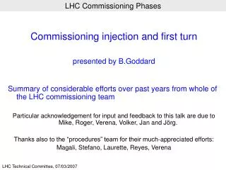
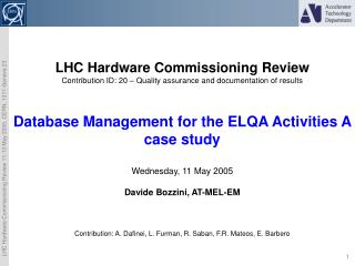
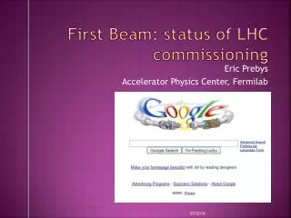
SPS example : before fit Since the SPS lattice is very simple, the model tune is set far away (0.2) from the actual tune in the example to make life a bit more difficult for the fit. Response for a horizontal and a vertical corrector (1% of the matrix). (*) + line : model Histogram : raw data MDHD.118 MDV.121 J. Wenninger – LHCCWG June 2006
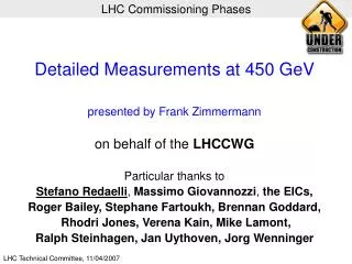
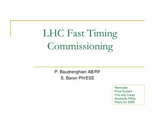
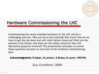
SPS example : a few fit iterations later… Details on SPS results can be found in CERN-AB-2004-009 • BPM and correctors are calibrated. • Fitted model tunes exactly as expected ! • Excellent agreement model-data. (*) + line : fit model (17 MAD parameters) with calibrated kick Histogram : gain corrected data Empty bin BPM rejected MDHD.118 MDV.121 J. Wenninger – LHCCWG June 2006
450GeV Initial Commissioning – Stage A.3.3 – Beam Dump (Pilot) • Set TCDQ & TCS • Adjust to best guess 10s based on current optics model & measured orbit • Requires collimator controls & application
Risk from particles in the abort gap • Asynchronous beam dump or over-populated abort gap quench or damage • Several failures possible (synchronisation, MKD erratic, abort gap repopulation) • Precautionary measures include: • Abort gap watchdog during the injection process, to inhibit injection with wrong phase • Abort gap monitor and possibility of abort gap cleaning • TCDS (fixed) – 6 m long diluter protects extraction septum • TCDQ/TCS (mobile) – 7 m long diluter kept at about 7-8 s from the beam, at all times
450GeV Initial Commissioning – Stage A.3.3 – Beam Dump (Pilot) • Set TCDQ & TCS • Adjust to best guess 10s based on current optics model & measured orbit • Requires collimator controls & application • Aperture Measurements • Horizontal aperture at TCDS entrance & MSD exit • Horizontal and Vertical aperture at MSD • Commission dump line Beam Instrumentation • BLMs, BPMs, BTVs & FBCTs • check all beam-dependent transient signals are acquired correctly for XPOC • Check position of bunch dumped • adjust energy tracking if needed local intervention to change EPROMS • adjust IPOC/XPOC references if needed
450GeV Initial Commissioning – Stage A.3.4 – BI (Pilot ++) • Commission Safe Beam Flag using 1Hz BCTDC intensity measurement • Verify the generation & distribution • Verify the logic at the LHC master BIC concerning the LHC safe beam flag • Commission the BCTFR in bunch to bunch mode • Set slot 1 to correspond to bunch 1 • Adjust the phase of the acquisition • Commission the Beam Presence Flag using BCTFR • Verify the generation & distribution • Commission the lifetime measurement • Will use turn by turn data from the BCTFR to calculate the lifetime • Lifetime initially updated at 1Hz
Early LHC BCT System Performance Third LHC Project Workshop, January 2005 - Rhodri Jones (CERN - AB/BI)
450GeV Initial Commissioning – Stage A.3.4 – BI (Pilot ++) • Commission the Tune Meter • Time-in the MKQ tune kicker • FFT analysis after applied excitation • MKQ – dedicated Q kicker • Chirp – either via BQK (BI tickler) or transverse damper • Commission Head-Tail Monitor • In parallel to Tune Meter with MKQ excitation • Allows more precise chromaticity measurement • Initial BLM System Commissioning • At this stage perform threshold adjustment on an “accidental quench & learn” basis • If quenches are very frequent then a more detailed study may be necessary • determine quench level for type of magnet which is quenching by steering beam into magnet?
BLM System at 450GeV • Already Commissioned • Hardware functionality & detector availability • First Adjustment of Thresholds • Initially set as factor 3 below estimated quench level at 450GeV • Based on • simulations • lab heating test measurements (SM18) • possible sector test data • Thresholds adjusted either on a • Quench & learn basis if too high • Dump & learn basis if too low • Threshold change procedure under discussion in MPWG • At 450GeV fast loss damage level is factor 1000 above quench level • No risk of damaging components LHCCWG, April 2005 - Rhodri Jones (CERN - AB/BI)
450GeV Initial Commissioning – Stage A.3.5 – Lifetime (Pilot ++) • Lifetime Optimisation • Use commissioned beam instrumentation to achieve reasonable lifetime • required for commissioning of remaining instrumentation • required for detailed optics measurements in next commissioning step
450GeV Initial Commissioning – Stage A.3.6 – BI (lifetime >1hr) • Systematic calibration of the BPMs & Correctors • Scan all orbit correctors and acquire all monitors • ~30 s per COD (530 CODs per beam) ~1 shift per beam • Check response data for BPM & COD polarities and calibrations • Use response data for a more detailed linear optics check • PLL • Requires BQK tune tickler or transverse damper in excitation mode • Wire Scanners • May need to slow them down to get desired resolution on a single bunch • 2m per second 180mm per point • Abort Gap • Commission the optics – will require tunnel intervention for fine adjustment • Define and check timing and injection bucket • Calibrate photon production versus proton number using a single bunch • Set threshold based on quench level in terms of protons/meter
System based on gated photomultiplier Tested in the SPS with synchrotron light source on fixed target beam Observation of injection kicker gap while beam is debunched before extraction. Worked extremely well Gain of photomultiplier is not as high as advertised Requires 15x more light For LHC a longer integration time is possible (every ms for SPS) BUT BSRA will require more light than anticipated at expense of BSRT Abort Gap Monitor (BSRA) LHC Machine Advisory Committee December 2006 - Rhodri Jones (CERN - AB/BI)
450GeV Initial Commissioning – Stage A.3.7 – Detailed Dump • Commission Beam Dependent Interlocks • Verify beam position interlock in IR6 (set to dump at > 3.2mm) • Verify count rates on BLM monitors at TCDQ (hardware link to dump) • Aperture Checks in IR6 • H: TCDS entrance, MSD exit, TCDQ, TCS • H&V: MKD, MSD, TCDQM (retract TCDQ) • Aperture Checks in the Dump Lines • Explicit check to ensure aperture is adequate for 14/15 MKD • Requires orbit bump in IR6 (cannot unplug 1 MKD) • Adjustment of Fine Kicker Timing • 2 bunches (bunch 1 & 2808) to define abort gap • Needs ‘new’ injection sequence and timing tables • UA access will be required for each trim
450GeV Initial Commissioning – Stage A.3.8 – Feedbacks • Commission Continuous Chromaticity Measurements • Requires RF radial modulation to be operational (~1Hz modulation) • Optimise PLL to track tune modulation of 1×10⁻⁴ • Commission Orbit Feedback • Use measured BPM & corrector calibrations • Use “best guess” optics model • Convergence time (i.e. correction rate) will depend on accuracy of the model • Commission Tune & Coupling Feedback • Verify trim quadrupole calibration (16 circuits per beam) • Verify trim skew quadrupole calibration (12 circuits B1 & 10 circuits B2) • Robust tune feedback requires coupling to be corrected! • Using commissioning tunes should help: 64.285/59.385
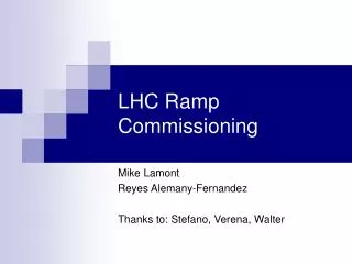
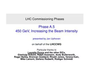
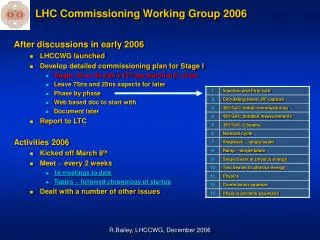
Tunes entirely defined by coupling Fully coupled Measurement of Coupling using a PLL Tune Tracker (RHIC Example) Third LHC Project Workshop, January 2005 - Rhodri Jones (CERN - AB/BI)
Coupling Feedback at RHIC (2006) LHCCWG, April 2005 - Rhodri Jones (CERN - AB/BI)
450GeV Initial Commissioning – Stage A.3.8 – Feedbacks • Start the commissioning of some collimators (TCPs) • Find the orbit position at the primary collimators and assign the aperture based on the best available optics estimates • Initial setting roughly 10 sigma • Rough setting up of injection protection devices • Find the orbit position at the protection devices and assign the aperture based on the best available optics estimates. • Lock the orbit with orbit feedback • Verify the centring of the TDI with circulating beam • requires masking of BLM thresholds at TDI • Set TDI to 10 sigma with the measured optics information • Set TCLI to 10 sigma with the measured optics information
Summary • Phase A.3 : • from a few hundred turns of circulating beam to a lifetime > 1 hr. • Main focus is on: • Continued RF commissioning • Initial beam dumping system commissioning • Full beam instrumentation commissioning • Consensus is to include time for commissioning of feedbacks at this stage • Ramp development is much easier if these feedbacks are operational • Basic optics measurements • At the end of this stage the machine should: • be ready for detailed optics measurements at 450GeV (next step) • have beam instrumentation and RF ready for ramping