Download
1 / 26
260 likes | 275 Vues
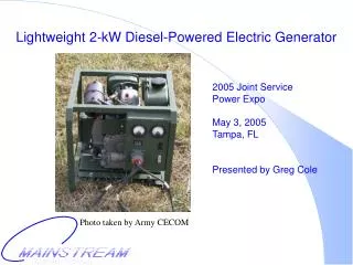
Providing a compact solution for military power needs, this generator offers portability and efficiency with its advanced technology optimized for weight reduction. It operates with diesel fuel and is designed for various field conditions, enhancing operational capabilities for armed forces.

E N D
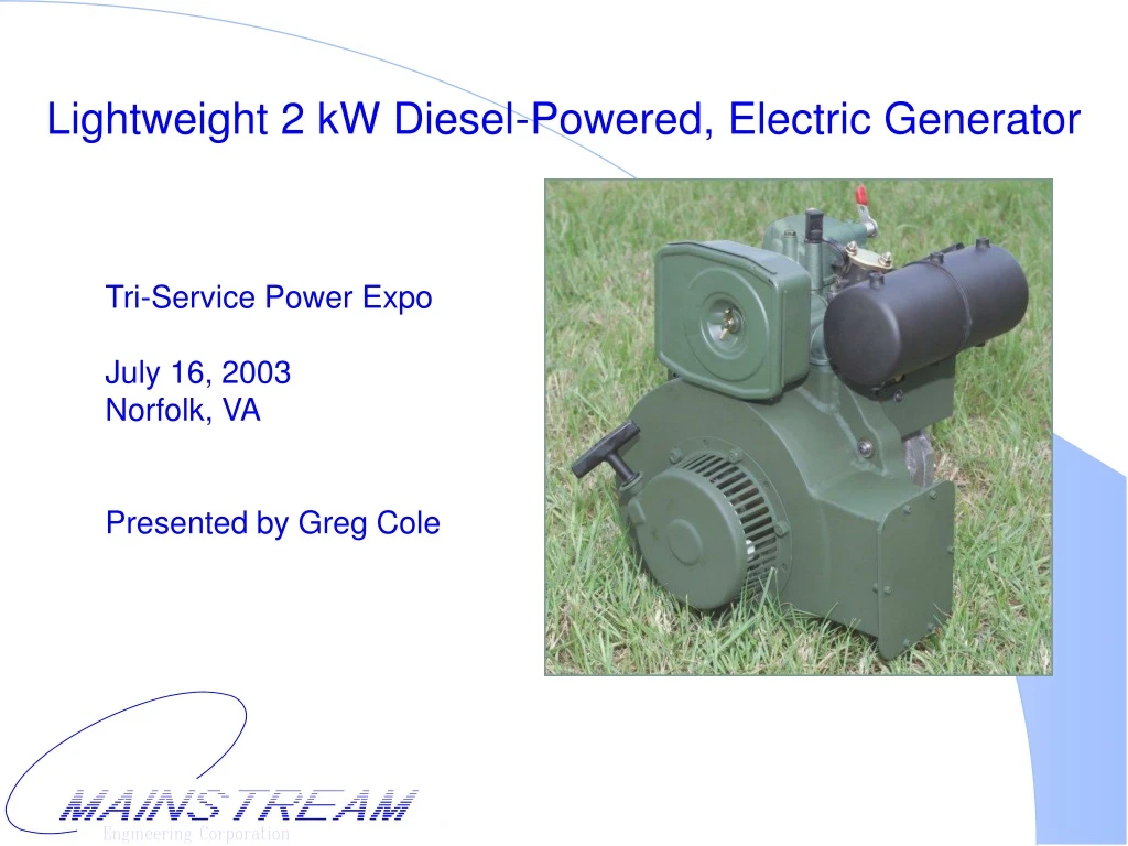
Lightweight 2 kW Diesel-Powered, Electric Generator Tri-Service Power ExpoJuly 16, 2003Norfolk, VAPresented by Greg Cole
Problem Statement • Post-Cold War military strategies include emphasis on lighter, more mobile, and more easily deployable armed forces • Standard DoD electrical generators are heavy • A lighter, more compact power source would benefit all branches of the armed services
Specific Need • Marine Corps System Command requires a man-portable power source to operate electronics and communications equipment for the Team Portable Collection System (TPCS) • Power is expected to exceed 1 kW @ 28 VDC • Desired weight is less than 50 lbs • Desired fuel is diesel
Baseline Technology • The DoD’s lightest, diesel-powered generator is the MTG • Model MEP-501A • 2 kW @ 28 VDC • 138 lbs • Model MEP-531A • 2 kW @ 120 VAC / 60 Hz • 158 lbs • MTGs are extremely heavy because a COTS engine is coupled with a COTS alternator Image from http://www.pmmep.org/technicaldata/2kw.htm
Solution • Mainstream’s lightweight generator is designed as an integrated unit and each component is optimized to reduce weight. • Weight reduction is primarily a result of: • an engine block fabricated with advanced engineering materials • integration of a permanent magnet alternator into the engine flywheel
Mainstream Engine • Only U.S. built diesel-engine in this size range • 4 generations of engines
Engine Features • Shaft Power: 2.8 kW • Cycle: 4-stroke, naturally-aspirated, compression-ignition, single-cylinder • Cooling: air-cooled • Starter: manual recoil
Integrated Alternator • Permanent magnets generate AC power that is rectified into DC power • Flywheel provides inertia required for reciprocating engine • Fan cools engine and alternator
Generator Size and Weight • Unmounted Generator • 14” (L) x 11” (W) x 16” (H) • 48 lbs • Backpack Generator • 18” (L) x 17” (W) x 20” (H) • 65 lbs
Generator Power: 2 kW @ 20-32 VDC Governor maintains nominal engine speed
Fuel Specification • Fuel Consumption: 0.23 gal/hr at full load • Fuel Types • Diesel • JP-5, JP-8, kerosene • Fuel Source • Line feed from tank or Jerry can • Optional on-board fuel tank available
Generator Noise • Baseline 2 kW MTG • 79 dBA at 25 ft • Mainstream 2 kW • 68 dBA at 25 ft
Generator Features • Instrumentation • Voltmeter • Ammeter • Hour meter • Power Receptacle • MS3450W32-17S • per MIL-C-5015G • Circuit Load Protection • Ground Terminal
Operating Environment • Temperature • Operating: -25°F to 125°F • Storage: -40°F to 158°F • Altitude • Operating: 10,000 feet • Storage: 40,000 feet • Angle of Inclination • 20° maximum
Frame Impact Test Results • Initial frame was modified A.L.I.C.E. backpack. • 740.3C Drop Test (Ends) • Passed six drops each from front, left, and right. • Bent during first five drops on back. • Cracked on sixth drop on back. • 740.2 Drop Test (Free Fall) • not performed
Frame Impact Test Results • Second frame • enclosed generator • thicker frame • 740.3C Drop Test (Ends) • Passed 6 drops each from front, back, left, right • 740.2 Drop Test (Free Fall) • Passed 6” and 12” test • Corners bent at 24” and 36”. • Base bent at 44” • Final frame • added cross brace • added folded base • welded instrument panel increases stiffness
Life Test Results • Version 1: Phase I generator • Prototype #1: 1000 hrs w/o any PM • Version 2: decreased weight / increased power • Prototype #2: 250 hrs without failure • Version 3: decreased weight • Prototype #3: failed after 37 hrs • Prototype #4: failed after 48 hrs • Version 4: improved reliability • Prototype #5: 476 hrs without failure (tests continue) • Prototype #6: field tested at Ft. Drum (on display)
Field Tests • Phoenix Warrior Field Exercise • Ft. Drum, NY • June 4-20, 2003 • U.S. Army 10th Mountain Division • U.S. Air Force 20th Air Support Operations Squadron
Field Test Results • “Size and weight of the generator is outstanding” • “Multi-fuel is great” • “Power output is good” • “Well built will take the pounding of the field” • “Site glass on fuel tank good idea” • “Runs noticeably quieter than the MIPS generator”
Field Test Results (cont.) • “The sliding throttle should be changed to one that is easier to adjust and allow for more precise adjustments.” • MEC is currently addressing this need. • “Slave receptacle would be nice for starting generator set and jump-starting the HMVV” • MEC is currently investigating this feature as an option. • “Voltage at startup is too high and could lead to equipment damage if personnel do not adjust throttle” • MCSC requires 32-20 VDC, 20th ASOS requires 30-20 VDC • MEC can provide optional voltage regulator
Program Status • Performance and life testing is complete on four generations of prototypes • Field testing by 20th ASOS is complete • Q3FY03-Q4FY03: Final test phase of program • continue life tests • MCSC field tests • Q4FY03: Product will be available • Q1FY04: MCSC plans to begin using generator for TPCS program
Contact Information • Company Address Mainstream Engineering Corp. 200 Yellow Place Rockledge, FL 32955 (321) 631-3550 http://www.mainstream-engr.com • Points of Contact • Technical: Greg Cole, gsc@mainstream-engr.com • Contracts: Michael Rizzo, mar@mainstream-engr.com
Demonstration • Location: Norfolk Waterside Marriott Parking Lot • Date: Wednesday, July 16 • Time: 2:45 PM