Download
1 / 26
260 likes | 303 Vues
The TRD Thermal Model provides a detailed representation of the thermal resistance network for the octagonal structure used in a space system. The current model is criticized for having too coarse data, like an optimistic heat conductivity assumption and an excessive number of heat dissipating nodes. This paper suggests improvements by reducing the number of heat dissipating nodes, increasing inner nodes, and recalculating realistic heat conductivity using a resistance network approach. Additional enhancements include incorporating various structural elements like straws, stiffeners, and fleece layers. The octagon is decomposed into slices and sections to better analyze heat distribution. Thermal coupling with heat sources is discussed, and worst-case scenarios are presented. The study aims to refine the model, considering radiational effects and additional factors not initially included.

E N D
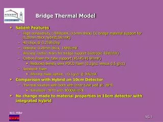
TRD Thermal Model Detailed Representation of the Thermal Resistance Network
OHB model too coarse • Allthough 82 heat dissipating nodes around the circumference of the octagon only one node in the center of the octagon • Too optimistic heat conductivity (12W/mK) into the interior of the octagon
Improvements • Reduction of the heat dissipating nodes to 18 but increase of the inner nodes to15 • More realistic heat conductivity caculated with resistance network
Assumptions • No cross heat transfer between the TRD straw modules • No heat transfer via radiation, only conduction
Elementary Cell • Endpiece sticking in the slits of the side panels of the octagon • Tubes (straws) • Longitudinal CFC stiffeners • Fleece on top of the straws • Section of the side panel same cross section as the fleece
Endpiece (+ Tubes and Stringer) Octagon Side Panel Section (+ Fleece) Endpiece (+ Tubes and Stringers) Equivalent Cross Section of 1 Straw Module
Network of 1 Straw Module Including Octagon Side Panel Section
Decomposition of Octagon • Split octagon into 3 slices • Lower slice modules in x • Center slice modules in y • Upper slice modules in x • Split each slice into 3 sections • Determine center of gravity • Imagine a line through the c.g. parallel to the straws • Put nodes in the c.g. and heat dissipating nodes in the peercing points of the line in the side panels
Split center sections another 2 times • Project the new c.g. points onto the imaginated line • This results in • 18 heat dissipating nodes and • 15 nodes to determine the temperatures
Build Model • Think of all modules within each section as parallel resistances • Calculate the resulting heat conductances • Sum heat produced on each side panel section and assign to the heat dissipating nodes
What is not in the model • No heat transfer between the modules in the directions perpendicular to the straw axes • No heat introduction from the lower face sheet of the upper cover • No heat introduction from the upper face sheet of the lower cover • No heat coming from the upper TOF
OHB Thermal Calculation Worst Hot Case : beta = +75°;YPR = -15/-20/-15 Worst Cold Case : beta = 0°; YPR = 0/0/-15 In 15 days from hot to cold (linear) MLI eff.emissivity = 0.03 Starting Temperature for the hot case from steady state runs ( averaged over 1 orbit)
Results from Steady State Runs PCB Temperatures : Hot Case : Tmin = +34,7° Tmax = +38,5° Tav = +36,6° Cold Case : Tmin = -19,8° Tmax = - 18,7° Tav = -19,2°
6. Results for different boundary conditions and MLI performances
Assume the influences of the above missing issues are small (OHB has to investigate yet): The results are not harmfull to the functionality of the TRD Missing issues are not small: Improve the model by including radiational effects of the covers and make more slices Run again Conclusion