Communication in Distributed Systems
Understand the importance of message passing in distributed systems and the layers of OSI model for effective interprocess communication. Learn about error detection and correction strategies like Hamming code and polynomial code checksum.

Communication in Distributed Systems
E N D
Presentation Transcript
The single most important difference between a distributed system and a uniprocessor system is the interprocess communication.
In a uniprocessor system, interprocess communication assumes the existence of shared memory. • A typical example is the producer-consumer problem. • One process writes to - buffer -reads from another process • The most basic form of synchronization, the semaphone requires one word (the semaphore variable) to be shared.
In a distributed system, there’s no shared memory, so the entire nature of interprocess communication must be completely rethought from scratch. • All communication in distributed system is based on message passing.
E.g. Proc. A wants to communicate with Proc. B • 1.It first builds a message in its own address space • 2.It executes a system call • 3.The OS fetches the message and sends it through network to B.
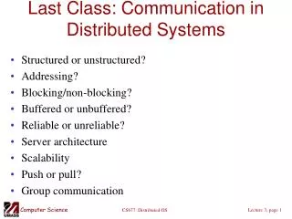
A and B have to agree on the meaning of the bits being sent. For example, • How many volts should be used to signal a 0-bit? 1-bit? • How does the receiver know which is the last bit of the message? • How can it detect if a message has been damaged or lost? • What should it do if it finds out? • How long are numbers, strings, and other data items? And how are they represented?
OSI (Open System Interconnection Reference model) Machine 1 Machine 2 Process A Process B Application protocol Application Application Presentation protocol Presentation Presentation Interface Interface Session protocol Session Sessionn Transport protocol Transport Transport Network protocol Network Network Data link protocol Data link Data link Physical protocol Physical Physical Network
The physical layer • This layer transmits the 0s and 1s. For example: • How many volts to use for 0 and 1 • How many bits per second can be sent • Whether transmission can take place in both directions simultaneously • The size and shape of the network connector • The number of pins and meaning of each one • It is physical layer’s job to make sure: send 0---receive 0 not 1.
The data link layer • This layer is to detect and correct errors in the physical layer. It groups the bits into frames, and see that each frame is correctly received. • The data link layer does its work by putting a special bit pattern on the start and end of each frame, to mark them, as well as computing a checksum by adding up all the bytes in the frame in a certain way. • The receiver recomputes the checksum from the data and compares the result to the checksum following the frame. If they agree, ok. If not, resend.
Error-detecting codes & Error-correcting codes • Two basic strategies have been developed to deal with errors in the transmission. • Error-detecting strategy: include only enough redundancy to allow the receiver to deduce that an error occurred, but not which error. • Error-correcting strategy: include enough redundant information along with each block of data sent, to enable the receiver to deduce what the transmitted data must have been.
A frame consists of m data bits and r redundant bits. Let the total length be n (n=m+r). An n-bit unit containing data and check bits is often referred to as an n-bit codeword. • Given any two codewords, say 100 and 101, it is easy to determine how many corresponding bits differ. Just use exclusive or. • The number of bit positions in which two codewords differ is called the Hamming distance.
Given the algorithm for computing the check bits, it is possible to construct a complete list of the legal codewords, and from this list find the two codewords whose Hamming distance is minimum. This distance is the Hamming distance of the complete code.
To detect d errors, you need a distance d+1 code because with such a code there is no way that d single-bit errors can change a valid codeword into another valid codeword. • To correct d errors, you need a distance 2d+1 code because that way the legal codewords are so far apart that even with d changes, the original codeword is still closer than any other codeword, so it can be uniquely determined.
An example is to append a single parity bit to the data. A code with a single parity bit has a distance 2, so it can detect single errors. • Another example is an error-correcting code of four valid codewords: 0000000000, 0000011111, 1111100000, and 1111111111. This code has a distance 5. It can correct double errors. If the codeword 0000000111 arrives, the receiver knows that the original must have been 0000011111.
If we want to design a code with m message bits and r check bits that will allow all single errors to be corrected, the requirement is: (m+r+1)<=2r.
Hamming code • Hamming code can correct single errors. • 1001000 • Hamming code: 00110010000 • 1100001 • Hamming code: 10111001001
Polynomial code checksum • Frame: 1101011011 • Generator: 10011, agreed by the send and the revceiver. • Message after 4 (the degree of the generator) zero bits are appended: 11010110110000 • 11010110110000 divide 10011 using modulo 2 division. The remainder is 1110. • Append 1110 to the frame and send it. • When the receiver gets the message, divide it by the generator, if there is a remainder, there has been an error.
The network layer • The primary task of this layer is routing, that is, how to choose the best path to send the message to the destination. • The shortest route is not always the best route. What really matters is the amount of delay on a given route. Delay can change over the course of time. • Two network-layer protocols: • 1) X.25 (telephone network) connection-oriented • 2) IP (Internet protocol) connectionless
The transport layer • This layer is to deliver a message to the transport layer with the expectation that it will be delivered without loss. • Upon receiving a message from the session layer • · The transport layer breaks it into pieces small enough for each to fit in a single packet • · Assign each one a sequence number • · Send them all • E.g. TCP, UDP
The session layer • This layer is essentially an enhanced version of the transport layer. • Provides dialog control, to keep track of which party is currently talking • Few applications are interested in this and it is rarely supported.
Presentation Layer • This layer is concerned with the meaning of bits. • E.g. people’s names, addresses, amounts of money, and so on.
The Application Layer • This layer is a collection of miscellaneous protocols for common activities such as electronic mail, file transfer, and connecting remote terminals to computers over a network.
Client-Server Model Request Client Server Reply Kernel Kernel Network
Client-Server Model Layer 7 6 5 4 3 2 1
Advantages • Simplicity: The client sends a request and gets an answer. No connection has to be established. • Efficiency: just 3 layers. Getting packets from client to server and back is handled by 1 and 2 by hardware: an Ethernet or Token ring. No routing is needed and no connections are established, so layers 3 and 4 are not needed. Layer 5 defines the set of legal requests and replies to these requests. • two system calls: send (dest, &mptr), receive (addr, &mptr)
An example of Client-Server • header.h • /* definitions needed by clients and servers.*/ • #define MAX_PATH 255 /* maximum length of a file name */ • #define BUF_SIZE 1024 /* how much data to transfer at once */ • #define FILE_SERVER 243 /* file server’s network address */ • /* definitions of the allowed operations. */ • #define CREATE 1 /* create a new file */ • #define READ 2 /* read a piece of a file and return it */ • #define WRITE 3 /* write a piece of a file */ • #define DELETE 4 /* delete an existing file */
/* Error codes. */ • #define OK 0 /* operation performed correctly */ • #define E_BAD_OPCODE –1 /* unknown operation requested */ • #define E_BAD_PARAM –2 /* error in a parameter */ • #define E_IO -3 /* disk error or other I/O error */
/* Definition of the message format. */ • struct message { • long source; /* sender’s identity */ • long dest; /* receiver’s identity */ • long opcode; /* which operation: CREATE, READ, etc. */ • long count; /* how many bytes to transfer */ • long offset; /* where in file to start reading or writing */ • long extra1; /* extra field */ • long extra2; /* extra field */ • long result; /* result of the operation reported here */ • char name[MAX_PATH]; /* name of the file being operated on */ • char data[BUF_SIZE]; /* data to be read or written */ • };
#include <header.h> • void main(void) • { • struct message m1, m2; /* incoming and outgoing messages */ • int r; /* result code */ • while (1) { /* server runs forever */ • receive(FILE_SERVER, &m1); /* block waiting for a message */ • switch(m1.opcode) { /* dispatch on type of request */ • case CREATE: r = do_create(&m1, &m2); break; • case READ: r = do_read(&m1, &m2); break; • case WRITE: r = do_write(&m1, &m2); break; • case DELETE: r = do_delete(&m1, &m2); break; • default: r = E_BAD_OPCODE; • } • m2.result = r; /* return result to client */ • send(m1.source, &m2); /* send reply */ • } • }
#include <header.h> • int copy (char *src, char *dst) /* procedure to copy file using the server */ • { struct message m1; /* message buffer */ • long position; /* current file position */ • long client = 110; /* client’s address */ • initialize(); /* prepare for execution */ • position = 0;
do { /* get a block of data from the source file. */ • m1.opcode = READ; /* operation is a read */ • m1.offset = position; /* current position in the file */ • strcpy(&m1.name, src); /* copy name of file to be read to message */ • send(FILE_SERVER, &m1); /* send the message to the file server */ • receive(client, &m1); /* block waiting for the reply */ • /* write the data just received to the destination file. */ • m1.opcode = WRITE; /* operation is a write */ • m1.offset = position; /* current position in the file */ • m1.count = m1.result; /* how many bytes to write */ • strcpy(&m1.name, dst); /* copy name of file to be written to buf */ • send(FILE_SERVER, &m1); /* send the message to the file server */ • receive(client, &m1); /* block waiting for the reply */ • position += m1.result; /* m1.result is number of bytes written */ • } while (m1.result > 0); /* iterate until done */ • return (m1.result >=0 > OK: m1.result); /* return OK or error code */ • }
Addressing • 1.the server’s address was simply hardwired as a constant • 2.Machine # + Process #: 243.4 199.0 • 3.Machine # + local-id • Disadvantage: it is not transparent to the user. If the server is changed from 243 to 170, the program has to be changed.
4. Assign each process a unique address that does not contain an embedded machine number. • One way to achieve this is to have a centralized process address allocator that simply maintains a counter. Upon receiving a request for an address, it simply returns the current value of the counter and increment it by one. • Disadvantage: centralize does not scale to large systems.
5. Let each process pick its own id from a large, sparse address space, such as the space of 64-bit binary integers. • Problem: how does the sending kernel know what machine to send the message to?
Solution: a.The sender can broadcast a special “locate packet” containing the address of the destination process. b. All the kernel check to see if the address is theirs. c. If so, send back “here I am” message giving their network address (machine number). Disadvantage: broadcasting puts extra load on the system.
6. provide an extra machine to map high-level (ASCII) service names to machine addresses. Servers can be referred to by ASCII strings in the program. • Disadvantage: centralized component: the name server
7. Use special hardware. Let process pick random address. Instead of locating them by broadcasting, locate them by hardware.
Blocking versus Nonblocking Primitives Client blocked Client running Client running Return from kernel, process released Trap to kernel, Process blocked Message being sent Blocking send primitive
Nonblocking send primitive Client blocked Client running Client running Return Trap Message being sent Message copied to kernel buffer
Nonblocking primitives • Advantage: can continue execution without waiting. • Disadvantage: the sender cannot modify the message buffer until the message has been sent and it does not know when the transfer can complete. It can hardly avoid touching the buffer forever.
Solutions to the drawbacks of nonblocking primitives • 1.To have the kernel copy the message to an internal kernel buffer and then allow process to continue. Problem: extra copies reduce the system performance. • 2. Interrupt the sender when the message has been sent Problem: user-level interrupts make programming tricky, difficult, and subject to race conditions.
Buffered versus Unbuffered Primitives • No buffer allocated. Fine if receive() is called before send(). • Buffers allocated, freed, and managed to store the incoming message. Usually a mailbox created.
Reliable versus Unreliable Primitives • The system has no guarantee about message being delivered. • The receiving machine sent an acknowledgement back. Only when this ack is received, will the sending kernel free the user (client) process. • Use reply as ack.
Acknowledgement • Long messages can be split into multiple packets. For example, one message: 1-1, 1-2, 1-3; another message: 2-1, 2-2, 2-3, 2-4. • Ack each individual packet Advantage: if a packet is lost, only that packet has to be retransmitted. Disadvantage: require more packets on the network. • Ack entire message Advantage: fewer packets Disadvantage: more complicated recovery when a packet is lost. (Because retransmit the entire message).
Some examples of packet exchanges for client-server communication REQ Client Server REP REQ Client Server ACK REP ACK REQ ACK AYA Client Server IAA REP ACK
Remote Procedure Call • The idea behind RPC is to make a remote procedure call look as much as possible like a local one. • A remote procedure call occurs in the following steps:
Remote procedure call steps: • The client procedure calls the client stub in the normal way. • The client stub builds a message and traps to the kernel. • The kernel sends the message to the remote kernel. • The remote kernel gives the message to the server stub. • The server stub unpacks the parameters and calls the server. • The server does the work and returns the result to the stub. • The server stub packs it in a message and traps to the kernel. • The remote kernel sends the message to the client’s kernel. • The client’s kernel gives the message to the client stub. • The stub unpacks the result and returns to the client.
Remote Procedure Call Client stub Server stub Client machine Server machine Call Pack parameters Unpack parameters Call Client Server Unpack result Pack result Return Return Kernel Kernel Message transport over the network