Download
1 / 29
290 likes | 425 Vues
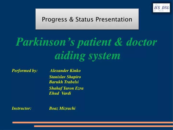
Parkinson ’s patient & doctor aiding system. Progress & Status Presentation. Performed by: Alexander Kinko Stanislav Shapiro Barukh Trabelsi Shahaf Yaron Ezra Ehud Vardi Instructor: Boaz Mizrachi. Project’s Basic Concept. USER PC Interface. Parkinson’s Patient.

E N D
Parkinson’s patient & doctor aiding system Progress & Status Presentation Performed by: Alexander Kinko Stanislav Shapiro Barukh Trabelsi Shahaf Yaron Ezra Ehud Vardi Instructor: Boaz Mizrachi
Project’s Basic Concept USER PC Interface Parkinson’s Patient PMD PC Interface PMD – Parkinson Mobile Device (*) PC (*) - There are 2 versions of PMD developed: minimal/basic (small box) & enhanced (big box).
Agenda • Functional description of the system • Description of performed project’s activities until now • Description of future project’s activities • Budget & Costs
Functional Description Of The System • Recognition of a unique nature of Parkinson’s tremor (2÷10 Hz). • Recognition of maximum 2 Parkinson’s attacks per minute. • Storing parameters (starting time, duration, strength, frequency) describing each Parkinson’s attack in the non-volatile on-device memory. • Optional notification to patient on appearing of Parkinson’s attack by: • Buzzer / LED indication • Vibration (enhanced system only) • Interconnection to PC for performing extended data processing and better tracking.
System’s Features • Autonomous portable system, that can be worn on the Parkinson’s patient wrist. There’s an option, to put it on other patient’s organs as well (head, leg, etc.). • Both systems (minimal and enhanced) are small: minimal system – 15x32x52mm, enhanced system – 18x43x68mm. • Minimal period for storing parameters - 7 days. • Power supply by 3 different sources: solar cell, rechargeable battery and USB. “Low-battery” state alert. • Communication with host PC by 2 different ways: IrDA & USB.
Functional Block Diagram Control Parkinson’s Tremor Indication Microcontroller Unit (MCU) System Debug Patient Accelerometer Pushbuttons LEDs Buzzer Vibration Motor PMD System Power IrDA Transceiver EEPROM USB IR Doctor PC - Doctor’s Application
System Block Diagram A Buzzer F# 1192551 (Murata) Vibration Motor Pushbuttons x3 x2 Infrared Rechargeable Battery LIR2450 @ 120 mAh LIR2032 @ 40 mAh IRDA Transceiver TFBS6711 (Vishay) USB Power 1-Mbit Serial EEPROM 25AA1024 (MicroChip) Accelerometer ADXL 345 (3-Axis) (Analog Devices) PIC Controller PIC24FJ256GB106 (MicroChip) PC Power Description: Big Box Small Box Power Manager BQ24032A (Texas Instruments) DC-DC TPS63020 (Texas Instruments) DC-DC TPS63020 (Texas Instruments) None Solar Cell 5V@5mA / 3V@10mA 5V@3mA
Performed Project’s Activities Until Now • Preliminary design and characterization of the system Hardware: • Found necessary hardware parts and devices for all features • Complete electrical design for both systems (minimal/basic and enhanced) • Detailed mechanical design with 3D model, ensuring all hardware parts can fit, for: • Small box • Big box • Layout and production for both systems (in progress) Software: • Basic programming modules
Software Development Tools • Before PMD is assembled & operational: • DM240011 - MPLAB Starter Kit for PIC24F • The Kit includes a compiler and a development environment. • It allowed us to develop basic modules. The followings were developed by using this tool: • Accelerometer module • EEPROM interface module • RTCC module • Digital BPF: FFT, basic frequency count algorithm • After PMD is assembled & operational: • Microchip MPLAB ICD 2 • For test and development rest of the software of PMD.
Chosen Enclosure Solution Small Box (OKW Enclosures) Big Box (OKW Enclosures) Body Material: ABS Body Material: ABS • External Height: 15 mm External Height: 18 mm • External Width: 32 mm External Width: 43 mm • External Depth: 52 mm External Depth: 68 mm • Unit Price: 7.13 US $ Unit Price: 9.02US $
Chosen Enclosure Solution (Continuation) Wrist Strap (OKW Enclosures) • Color: Black • Length: 280 mm • Material: Elastic • Unit Price: 11.55 US $
PCB Production • Stack-up • Layout • BOM - Bill Of Materials • Production - this week Assembly of boards First electrical tests
Stack-up Signal Layer #1 (Top) GND Layer 1 mm VCC Layer Signal Layer #2 (Bottom)
Layout Of PCB For Small Box Parts Placement (Top) Parts Placement (Bottom) Layer #1 Top Plane Layer #4 Bottom Plane Layer #2 GND Plane Layer #3 VCC Plane
Layout Of PCB For Big Box (Preliminary) Parts Placement (Top) Parts Placement (Bottom) • Notes: • This is preliminary placement only • The routing will be performed immediately • after final placement will be finished
HW (Barukh & Stas + Alex’s assistance) Defining assembly process of PCBs Performing of basic electrical tests Initialization and checking interface between different hardware elements SW (Embedded System) (Barukh & Stas) Flowchart of the software Defining communication’s interface Creating mini drivers for all parts of the system Operation of mini system Adding communication interface Gradual integration for additional modules Complete software solution for embedded system Future Project’s Activities
SW (Embedded System - Communication) (Yaron & Ehud) Learn Microcontroller & electrical circuit Learn IR & USB communication protocols Define data structures Write PIC’s program, that will enable communication by IR and USB SW (PC/Doctor’s Application) (Yaron & Ehud + Barukh & Stas) Write IR and USB drivers for the PMD Doctor’s Application Future Project’s Activities (Continuation)
Future Milestones • Electrical tests • Defining communication protocol between embedded device and PC • Setting up mini system (embedded hardware & software) and presentation of software analysis • Creating mini drivers for different devices in the system • Establishing communication with the PC • Integration between mini system and communication with the PC • Presentation of mini system
Gantt Chart HW Preliminary electrical tests (End of part A) SW Completed mini system (HW & SW) Communication Presentation of complete system Definition of communication protocol Communication with PC
Estimated Costs • PCB: 610 $ (Including Tooling) • Basic/Minimal System • (for each): 85 $ • Enhanced System • (for each): 100 $ • Layout and board assembly will be performed in the Lab