Steffes Engineered Flare System
Steffes Engineered Flare System. Presented by Todd Mayer, Steffes Corporation. Steffes Engineered Flare System Agenda. Why discuss this? Regulations put in place last year that required operators to look at gas being vented or burned on their production sites


Steffes Engineered Flare System
E N D
Presentation Transcript
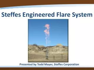
Steffes Engineered Flare System Presented by Todd Mayer, Steffes Corporation
Steffes Engineered Flare System Agenda Why discuss this? Regulations put in place last year that required operators to look at gas being vented or burned on their production sites Clarification of the specific gases are we talking about Types of devices for burning the gases Types of devices required for given production levels How has Steffes addressed these regulations? Development of the Steffes Engineered Flare system that will be 3rd party tested in June 2012. This is only one option available to operators. Combustor, air assist flares, gas assist flares, and multi-orfice flares (not discussing today)
What regulations were put in place requiring operators to look at gas being vented or burned on their production sites? Bakken Pool Oil and Gas Production Facilities Air Pollutions Control Permitting & Compliance Guidance Document Issued by ND Department of Health, Division of Air Quality Effective Date May 2, 2011
2 Main Requirements need to be met: The overall well Potential to Emit (PTE) of VOC, CO, and Nox needs to be less than 100 Tons per Year (TPY) Greater than 100 TPY requires a permit to construct and Title V application. Oil Tank Potential to Emit (PTE) of VOCs: Tank PTE < 20 TPY—Ground Flare Acceptable Tank PTE >20 TPY—Utility Flare Required What regulations were put in place requiring operators to look at gas being vented or burned on their production sites?
What are VOCs? Volatile Organic Compounds Organic Compounds—Compounds containing carbon One way to destroy VOCs is to burn them using flares. One way flares are rated is their Destruction and Removal Efficiency (DRE). A flare with a 98% DRE is burning 98% of the VOCs contained in the incoming gas.
Sources of VOCS on an Oil Site Oil/Condensate Tanks Produced Water Tanks Treater Flares Heater/Burners Truck Loading Reciprocating Internal Combustion Engine (RICE) Pneumatic Pumps Pneumatic Controllers Today we will focus on VOCs from tanks and treater flares
Burning VOCs North Dakota specifies 3 classifications of devices for burning VOCs: Ground Pit Flare (includes, but not limited to pit flares or shop built flares). 90% DRE allowed. Enclosed Smokeless Combustor. 98% Destruction and Removal Efficiency (DRE) allowed. Utility Flare or Other 98% DRE device At a minimum, all treater gas and tank gas must be burned with a ground pit flare. We will be focusing on the utility flare (the Steffes Engineered Flare is a utility flare) today.
Definition of a Utility Flare (reference 40 CFR 60.18) Operates with no visible emissions (smoke) except for periods not to exceed a total of 5 minutes during any 2 consecutive hours. Operates with a flame present at all times. Gas exits the flare at a velocity within a specified range.
What control device is needed on a particular site? The overall well Potential to Emit (PTE) of VOC, CO, and Nox: Needs to be less than 100 Tons per Year (TPY). Greater than 100 TPY requires a permit to construct and Title V application. Oil Tank Potential to Emit (PTE) of VOCs: Tank PTE < 20 TPY—Ground Flare Acceptable Tank PTE >20 TPY—Utility Flare Required What does all this mean in terms of production numbers?
Example: A well produces an average of 500 bopd during its first month of production. A ground flare is not acceptable because flow is greater than 118 bopd. Allowable treater gas to be burned is 663 mscfd if burned with a utility flare (98% DRE) or 154 mscfd if burned with a ground flare (90% DRE). 118 bopd limit for using a ground pit flare (90% DRE) on tank gas. Above this limit, VOC emissions would be greater that 20 TPY. • Included in analysis (default values from state): • Treater Flare Gas, Tank Vent Gas, Treater Burner • And Truck Loading 98% DRE Tank Gas, 98% DRE Treater Gas 98% DRE Tank Gas, 90% DRE Treater Gas 90% DRE Tank Gas, 90% DRE Treater Gas 90% DRE Tank Gas, 98% DRE Treater Gas
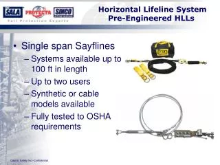
What is a Steffes engineered flare? One system to burn both tank and treater gas. Both burners qualify as utility flares (98% DRE). Also possible to use each burner as a stand alone system Includes ignition system and monitored standing pilot Handles a wide range of gas flow rates Open Flare Meets all requirements of EPA 40 CFR 60.18 Smokeless Flame present at all times Exit Velocity Requirements Simple, Reliable, Easy to Maintain, and Safe A flare that does not run destroys 0% of VOCs Easy to set-up. Everything is included to make the system work. Options to log or communicate with existing SCADA systems.
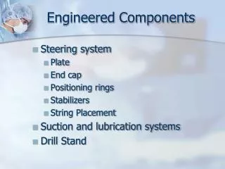
Ignition, Data Logging, and Monitoring Optional pressure gages for system monitoring High Temperature Insulated Stainless Steel Conductor Electric Fencer or Burner Management System to provide high voltage pulse to igniter Thermocouple Data Logger or SCADA interface Powder Coated Steel Stands
Flare and Pilot Tips Low Pressure Tank Gas Tip. 4 osi High Pressure Treater Gas Tip. 3-8 psi. All tips are modular meaning that it is possible to configure to only burn treater gas or to only burn tank gas. Standing Pilot 8-10 psi
High Pressure Flare Tip The high pressure flare tip is a pressure assisted flare. When gas exits under pressure at a higher velocity than a typical pit flare, it burns with a pale orange smokeless flame. 3. Gas exits through the annular gap and is guided upward by the plunger radius. As the gas is guided around the radius, significant combustion air is drawn in prior to ignition. 2. Plunger lifts a distance proportional to the gas flow. 1. Gas fills main barrel of flare and builds to a pressure of 3 psi. This pressure is based on the weight of the plunger and preload of spring pack.
Low Pressure Flare Tip Similar operation to the high pressure flare tip, but needs to operate at a much lower pressure to handle tank vent gas. 3. Gas exits through the annular gap and is guided upward by the plunger radius. As the gas is guided around the radius, significant combustion air is drawn in prior to ignition. 2. Plunger lifts a distance proportional to the gas flow. 1. Gas fills main barrel of flare and builds to a pressure of 4 osi. This pressure is based on the weight of the plunger only.
Pilot System High Temperature Ignition Rod High Temperature Thermocouple Thermocouple Looking in end of pilot nozzle Ignition Conductor Pilot Gas
Steffes Engineered Flare Low Pressure Tank Gas High Pressure Treater Gas Pilot
Engineered Flare System Flare Tips in Berm Electric Fencer
Low Pressure Flare Tip Burning Approximately 30 mscfd Low Pressure Tank Vent Gas Flare Tip Pilot
Summary Today we have discussed regulations that are in place guiding operators on what needs to be done with gas emitted from production oil sites. The Steffes Engineered Flare is one tool that is available to help operators meet these regulations. The system will be 3rd party tested in June 2012. Steffes is working with customers to develop other flaring technologies such as air assist flares, gas assist flares, and multi-orifice flares. More technologies will be introduced as regulations continue to evolve.