Download
1 / 43
430 likes | 451 Vues
Impact of Directional Antennas on Ad Hoc Routing. Romit Roy Choudhury Nitin H. Vaidya. Ad Hoc Networks Typically assume Omnidirectional antennas. A silenced node. C. B. A. D. Using Directional Antennas …. Spatial reuse increases Wireless interference reduces Range extension possible

E N D
Impact of Directional Antennas on Ad Hoc Routing Romit Roy Choudhury Nitin H. Vaidya
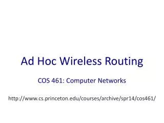
Ad Hoc NetworksTypically assume Omnidirectional antennas A silenced node C B A D
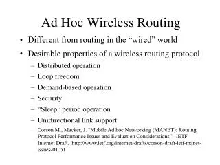
Using Directional Antennas … • Spatial reuse increases • Wireless interference reduces • Range extension possible • MAC layer performance shown to improve. [Zander, Ramanathan, Takai, RoyChoudhury, Kalyanaraman] C B D A C B D A
Are directional antennas also beneficial to ad hoc routing ?Do routing protocols need to be adapted to suit directional antenna systems ?
This Paper • Proposes a simple DiMACprotocol • Evaluates impact of DSR over DiMAC • Identifies keytradeoffs • Proposes optimizations to suit directional antennas – Directional DSR (DDSR) • Discusses issues where directional antennas may or may not be suitable
Antenna Model 2 Operation Modes: OmniandDirectional A node may operate in any one mode at any given time
Antenna Model In Omni Mode: • Nodes receive signals with Gain Go • While idle a node stays in Omni mode In Directional Mode: • Beamforms in any one of N static beams (switched) • Directional Gain Gd(Gd > Go)
RTS CTS Directional MAC – DiMAC • A node listens omni-directionally when idle • Sender transmits Directional-RTS (DRTS) – Receiver receives RTS in the omni mode (DO links) • Receiver sends Directional-CTS (DCTS) • DATA,ACK transmitted and received directionally B C
Data ACK Directional MAC – DiMAC • A node listens omni-directionally when idle • Sender transmits Directional-RTS (DRTS) – Receiver receives RTS in the omni mode (DO links) • Receiver sends Directional-CTS (DCTS) • DATA,ACK transmitted and received directionally B C
Directional MAC – DiMAC • Directional Network Allocation Vector (DNAV) • Defer only in the direction of ongoing communication • Broadcast implemented through sweeping • Beam Handoffs (due to node mobility) handled through scanning • Send probe packets on recently used beams • Update neighbor cache based on replies to probes
Routing Protocols • Many routing protocols for ad hoc networks rely on broadcast messages • For instance, flood of route requests (RREQ) • Using omni broadcast will not discover far-away neighbors • Need to implement broadcast using directional transmissions • A directional transmission, Omni reception = DO link
Dynamic Source Routing[Johnson] • Sender floods RREQ through the network • Nodes forward RREQs after appending their names • Destination node receives RREQ and unicasts a RREP back to sender node, using the route in which RREQ traveled
Route Discovery in DSR Y Z S E F B C M L J A G H D K I N Represents a node that has received RREQ for D from S
Route Discovery in DSR Y Broadcast transmission Z [S] S E F B C M L J A G H D K I N Represents transmission of RREQ [X,Y] Represents list of identifiers appended to RREQ
Route Discovery in DSR Y Z S [S,E] E F B C M L J A G [S,C] H D K I N
Route Discovery in DSR Y Z S E F [S,E,F] B C M L J A G H D K [S,C,G] I N • Node C receives RREQ from G and H, but does not forward • it again, because node C has already forwarded RREQ once
Route Discovery in DSR Y Z S E F [S,E,F,J] B C M L J A G H D K I N [S,C,G,K] • Nodes J and K both broadcast RREQ to node D
Route Reply in DSR Y Z S RREP [S,E,F,J,D] E F B C M L J A G H D K I N Represents RREP control message
DSR over DiMAC • DiMAC broadcast – RREQ transmitted sequentially on all N beams – sweeping • Sweeping allows DO links • Higher delay • Higher Overhead
Tradeoffs Higher tx range Fewer hop routes Lower end to end delay Fewer link failures Narrow beamwidth Narrow beamwidth High sweeping delay High sweeping overhead Frequent handoffs Motivation to evaluate impact of directional antennas on routing
Evaluation • Simulation • Qualnet simulator 3.1 • Constant Bit Rate (CBR) traffic • Packet Size – 512 Bytes • 802.11 transmission range = 250meters • Channel bandwidth 2 Mbps • DSR DSR + 802.11 + Omni Antenna • DDSRx DSR + DiMAC + x-Beam Antenna • E.g., DDSR6 DSR over DiMAC, with beamwidth = 60 degrees
Route discovery latency …Single flow, grid topology (200 m distance) DDSR4 DDSR6 DSR
Throughput DDSR18 DDSR9 DSR
Observations • Advantage of higher transmit range significant only at higher separation between source-destination • Grid distance = 200 m -- thus no gain with higher tx range of DDSR4 (350 m) over 802.11 (250 m). • However, DDSR4 has sweeping delay. Thus route discovery delay higher • Sub-optimal routes chosen by DDSR because destination misses shortest RREQ, when beam-formed
Sub-optimal Routes in DDSR F J RREP J D K N RREQ D receives RREQ from J, and replies with RREP Meanwhile, D misses RREQ from K – called Deafness
Delayed RREP Optimization • Due to sweeping – earliest RREQ need not have traversed shortest hop path. • RREQ packets “sweep-ed” to different neighbors at different points of time • If destination replies to first arriving RREP, it can miss shorter-path RREQ • Optimize by having DSR destination wait before replying with RREP • Waiting allows destination to gather all early RREQs
Bridging “Voids” using DDSR For randomly located nodes Using DDSR can be beneficial in sparse networks. Higher transmission range of directional antennas can communicate across “voids” in the topology.
Routing Overhead • Using omni broadcast, nodes receive multiple copies of same packet – Redundant • Broadcast Storm Problem • Using directional Antennas – can do better ? • Forward packets radially outward
Selective-Forward Optimization Use K antenna elements to forward broadcast packet. K = N/2 in simulations (No. Ctrl Tx) (Footprint of Tx) No. Data Packets Footprint of Tx Ctrl Overhead =
Selective-Forward Optimization Control overhead reduces Beamwidth of antenna element (degrees)
Mobility • Link lifetime increases using directional antennas. • Higher transmission range - link failures are less frequent • Handoff: Nodes moving out of beam coverage in order of packet-transmission-time • Low probability
Mobility • Antenna handoff • If no response to RTS, MAC layer uses n adjacent antenna elements to transmit same packet • Route error avoided if communication re-established [RoyChoudhury02UIUC Techrep]
Observations • Randomness in topology aids DDSR. • Voids in network topology bridged by higher transmission range (prevents partition) • Higher transmission range increases link lifetime – reduces frequency of link failure under mobility • Antenna handoff due to nodes crossing antenna elements – not too serious
Future work • Directional route repair possible in DDSR • Incorporate Anycasting in DDSR • Reducing route alignment • Choosing zig-zag routes increase spatial reuse • Power control based on the knowledge of neighborhood
Conclusion • Directional antennas can be beneficial to routing • Fewer hop-count • Bridges network “voids” in sparse scenarios • Higher link lifetime • However tradeoffs exist • Broadcast overhead higher • Handoffs possible when node moves beam beams • Deafness can cause sub-optimality
Conclusion • Evaluation shows DDSR better than DSR when • Sparse networks • Large src-dest separation • Moderately narrow beamwidth
Thank you www.crhc.uiuc.edu/~nhv
Issues • Broadcast storm: Using broadcasts, nodes receive multiple copies of same packet Optimize by using K out of N beams to forward broadcast packets
Performance • Results indicate that routing performance can be improved using directional antennas
F J J D K N RREP RREQ Issues: Sub-optimal Routes • Due to sweeping, shortest path RREQ may reach destination late • Sub-optimal routes may be chosen if destination node misses shortest request, while beamformed D receives RREQ from J D beamforms to send RREP D misses RREQ from K Using Omni, D gets all RREQs
Performance Throughput Vs Mobility Control overhead • Control overhead higher using DDSR • Throughput of DDSR higher, even under mobility • Latency in packet delivery lower using DDSR