Download
1 / 25
280 likes | 486 Vues
This document outlines the electroplating processes and materials involved in fabricating Ni/Au layers, emphasizing the critical role of nickel (Ni) diffusion in maintaining wirebond integrity. It details the sequence of plating, the layers involved (Ni Strike, Ni Plate, Au Strike, Au Plate), and the necessary etching activation for optimal bonding to underlying substrates such as copper (Cu). The interaction of Ni with the atmosphere and its implications during die attach heat exposure are explored. Recommendations for minimizing Ni diffusion and optimizing Au grain size are provided to enhance wirebond yield.

E N D
Electroplated Ni/Au: Limiting Ni Diffusion Jonathan Harris CMC Laboratories, Inc. Tempe, Arizona
Plating Sequence Etch Activation Ni Strike (5 µinch) Ni Plate (100-200 µinch) Au Strike (5 µinch) Au Plate (20-100 µinch) (NiCl2·6H2O) and Ni(SO3NH2)2- role to bond well to layer below (e.g. Cu) K(Au(CN)2) type III (99.9% Au purity) role to plate high purity Au layer K(Au(CN)2) (99.9% Au purity) role to keep impurities out of the Au plating bath Nickel sulfamate Ni(SO3NH2)2 – role to form thick Ni layer H2SO4 for Cu- Etch off Cu-Oxide
Metal Stack Up and Chemistry Plated Ni (3-5 µm) Plated Au (1-2 µm) W Co-fire Metal
Typical Assembly Sequence • Plated package (Ni/Au) • Die attach (high power applications) • AuSn at >280C for 3-5 minutes under forming gas shroud • AuSi at > 380 C for 3-5 minutes under forming gas shroud • GGI bonding at 250C for > 30 minutes in air • Wirebond to Au surface (Au or Al) –wirebonding after heat exposure of plated layer from die attach
Wirebond Yield vs. Ni(oxide) on Au Surface Au wirebond onto plated Ni/Au surface Wirebond lifts (%) vs. Atomic % Ni on Au Surface (Auger Analysis) Data from Duane Endicott, Motorola (Casey and Endicott, Plating and Surface Finishing, V67, July 1980, pg. 39) Wirebonding requires less than 2% Ni on Au surface
Sources for Ni on Au Surface • Ni “drag-out” impurities in Au bath that co-plated with Au • Ni plating solution that is not rinsed completely and builds up as contamination in Au bath • Present but can be minimized with effective Au strike • Ni from Ni under-layer that diffuse through the Au layer during die attach heat exposure
Ni Diffusion in Au • Ni diffusion into the Au layer driven by increase in entropy • Ni diffusion and concentration on the Au surface driven by Ni reaction with the atmosphere • Oxygen atmosphere: Ni + O2 NiO (ΔH= -244 KJ/m) • Results in surface segregation of Ni on Au • Forming gas shroud slows but does not eliminate this reaction
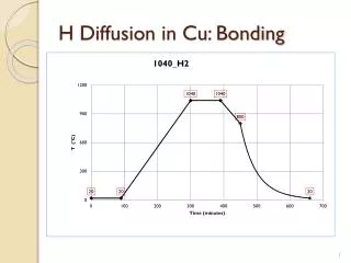
Diffusion of various metals in Au Hall and Morabito, Thin Film Solids, Vol 53, 1978 Grain boundary diffusion rates 7 orders of magnitude higher for Ni at 200C along grain boundaries than through bulk. To limit Ni diffusion, must limit grain boundary diffusion.
To Limit Ni on Au Surface for Wirebond Yield…. • Limit the level of Ni grain boundary diffusion in the Au layer • Limit the reactivity of the atmosphere during the die attach with Ni (limit oxygen)
Altering Au Microstructure using Electro-plating Conditions to Minimize Ni Diffusion
How Do Electroplated Layers Grow? • Diffusion of M+ ion to cathode where electrochemical reduction occurs M+ + e M • M atoms diffuse on cathode surface until critical nuclei is formed • Subsequent M atoms either grow on existing nucleated grain or initiate new nuclei • Intersection of growing grains generally form grain boundaries
Grain nucleation and growth study, Au film on single crystal Fe • Atoms deposit randomly • Diffuse until multiple atoms collide to form a cluster • This represents the film nucleation • Clusters then grow to form grains • Cluster/grain intersection points become grain boundaries TEM of Au film growth on Fe, Kamasaki, 1974
For Larger Grain Microstructure… • Limit the nucleation rate for the growing film • “Encourage” incident atoms to add to existing grains vs. nucleate new grains • = Limit the rate of deposition of M atoms • = Limit the diffusion rate of M+ ions to the cathode surface • = For example, lowering the overall plating current density will increase grain size (but also increase cost due to reduced plating rate)
Approach to Growing Large, Dense Au Grains Acceptable plating rate Multiple controls over Au plating process
Structure of the Electrolyte During Plating • Plating process is dynamic • Deplete metal ions as M+ are reduced at the cathode • Results in thin layer of (-) ions very close to the cathode • Results in depletion of M+ in diffusion layer
Plating Potential • With no current flowing, electrochemical potential is established Eo • During plating Ep = Eo + η • η “electrochemical over-potential” • η (cathode) = η (diffusion) + η (activation) • η (diffusion) = energy to diffuse metal ion through electrolyte diffusion layer to electrode surface • η (activation) = activation energy to reduce the atom, atomic surface diffusion to form nuclei
Plating Potential and Film Nucleation Rate • Increasing η (activation) • Decreases nucleation rate • Makes it more energetically unfavorable to initiate new nucleation sites • At some point will make plating inefficient • Increasing η (diffusion) • Decreases the nucleation rate • Makes it more energetically unfavorable to move an M+ ion to the cathode surface • May also make plating inefficient if plating rate is limited to an impractical level
Plating Scheme for Large Au Grains • Add a Pb at ppm level to Au plating bath • Pb2+ ion which will not be reduced during Au deposition • Reside near the cathode and decrease the magnitude of the M+ depletion during plating • Increase η (diffusion) which will decrease Au2+ diffusion in solution • As Pb2+ builds up near cathode, becomes barrier to Au2+ diffusion to surface • Decrease nucleation density • To control this level of Pb2+ build up– implement “pulse plating”
Pulse Plating • Alternate cathodic pulse with no current flow period • During “on” pulse • Ionic diffusion patterns form • M+ ions plate • Pb+ “grain refiners” align near the cathode • M+ ion become depleted near the cathode • During “off” pulse • Ionic diffusion patterns re-randomize • Pb+ ions diffuse away from cathode surface • M+ ions can diffuse back toward the cathode surface • Pulse plating cycle can be used to mitigate and control impact of M+ depletion and Pb+ “grain refiner” build up
Pulse Plated with ppm Pb Additive DC Plated Au
Uniform but small grains- high Ni diffusion due to very high Au grain boundary density Non-uniform mixed small and large grains. Some improvement in grain boundary density Large Uniform Au Grains minimize Ni grain boundary diffusion
Auger spectra, Au with small grain size, 250C for 10 minutes Ni concentration is 9.2% Ni concentration < 1.0%
Summary • Combination of ppm level Pb addition to plating bath and pulse plating can produce large, dense Au grains • Pb level, pulse magnitude and frequency can be used to control Au microstructure • Manipulate energetics of ion diffusion in solution and reduction at the cathode • Large grains effective barrier to Ni diffusion