Download
1 / 49
590 likes | 1.01k Vues
HIGH VOLTAGE DIRECT CURRENT TRANSMISSION. BULK TRANSMISSION OF ELECTRICAL POWER. History. First commercial application of HVDC between Swedish mainland and the island of Gotland in 1954. Underwater link of 90 km and 20 MW. After the advent of thyristor convertor,

E N D
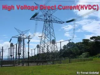
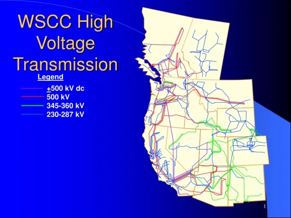
HIGH VOLTAGE DIRECT CURRENT TRANSMISSION BULK TRANSMISSION OF ELECTRICAL POWER
History • First commercial application of HVDC between Swedish mainland and the island of Gotland in 1954. • Underwater link of 90 km and 20 MW. • After the advent of thyristor convertor, • New Brunswick and Quebec 320 MW back-to-back DC interconnection commissioned in 1972. • With reduced size, cost and improved reliability of power electronic converters, has made HVDC transmission more widespread. • In North America, total HVDC transmission capacity in 1987 was 14,000 MW.
Advantages • In a number of applications HVDC is more effective than AC transmission. Examples include • Undersea cables, where high capacitance causes additional AC losses. (e.g. 250 km Baltic Cable between Sweden and Germany) • Long power transmission without intermediate taps. • Example, in remote areas • Power transmission and stabilization between unsynchronized AC distribution systems • Connecting a remote generating plant to the distribution grid • Reducing line cost: 1) fewer conductors 2) thinner conductors since HVDC does not suffer from the skin effect • Facilitate power transmission between different countries that use AC at differing voltages and frequencies • Synchronize AC produced by renewable energy sources
Disadvantages • The disadvantages of HVDC are in conversion, switching and control. • Expensive inverters with limited overload capacity • Higher losses in static inverters at smaller transmission distances • The cost of the inverters may not be offset by reductions in line construction cost and lower line loss. • High voltage DC circuit breakers are difficult to build because some mechanism must be included in the circuit breaker to force current to zero, otherwise arcing and contact wear would be too great to allow reliable switching.
UNIT I INTRODUCTION Book Ref : 1. Padiyar , K. R., “HVDC power transmission system 2. Edward Wilson Kimbark, “Direct Current Transmission
INTRODUCTION • Modern DC power transmission is relatively a new technology which made a modest beginning in the year 1954. • The advent of thyristor valve is the improvements over last 18 years has been responsible for the acceleration of the growth of HVDC technology. • Improving reliability and reducing cost of converter stations. • The latest development of multi-terminal system operation has increased the scope of application of HVDC systems • While it is true that the HVDC systems are quite reliable and converter control allows flexibility in the system operation.
COMPARISON OF AC AND DC TRANSMISSION The relative merits of two modes of transmission (ac & dc) which need to be considered by a system planner are based on the following factors: • Economics of transmission • Technical performance • Reliability
ECONOMICS OF POWER TRANSMISSION • Cost of transmission • Insulators • Line compensation • Cost of Compensation • Converters and Filters.
ECONOMICS OF POWER TRANSMISSION • The cost of transmission line includes the investment and operational costs. • The investment includes costs of Right of Way (ROW), transmission towers, conductors, insulators and terminal equipment. The operational costs include mainly the cost of losses. • The characteristics of the insulators vary the type of voltage applied. • For simplicity, if it is assumed that the insulator characteristics are similar for ac & dc and depend on the peak level of the voltage applied with the respect to the ground. • Then it can be shown that for lines designed with the same insulation level, a dc line carry as much power with two conductors (with positive and negative polarities with respect to ground) as an ac line with three conductors for the same size. • This implies that for a given power level dc line requires less ROW, simpler and cheaper towers and reduced conductor and insulation costs.
The power losses are also reduced with dc as there are only two conductors. • The absence of skin effect with dc is also beneficial in reducing power losses marginally. • The dielectric losses in case of power cables is also very less for dc transmission. • The corona effects tend to be less significant on dc conductors than for ac and this also leads to the choice of economic size of the conductors with dc transmission. • The other factors that influence the line cost are the cost of compensation and terminal equipment. • Dc lines do not require compensation but the terminal equipment costs are increased due to the presence of the converter and filters.
Ac tends to be more economical than dc for distance less than break even distance and costlier for longer distances. • The break even distance can vary from 500 to 800 km in overhead lines depending on the per unit line costs.
TECHNICAL PERFORMANCE • The DC transmission has some positive feature which are lacking in AC transmission. These are mainly due to the fast controllability of power in DC lines through converter control. • The following are the advantages: • Full control over power transmitted. • The ability to enhance transient and dynamic stability in association AC networks. • Fast control to limit fault currents in DC lines. These make it feasible to avoid DC breakers in two terminal DC links.
In addition, the DC transmission overcomes some of the problems of AC transmission. These are described further: • Stability Limits • Voltage Control
STABILITY LIMITS • The power transfer in AC lines is dependent on the angle difference between the voltage phasors at the two ends. • For a given power level, these angle increases with distance. • The maximum power transfer is limited by the considerations of steady state and transient stability.. • The Figure shows the power capability of the DC lines which is unaffected by the distance of transmission, and only its limited by the current carrying capacity of the conductors(Thermal Limit )
VOLTAGE CONTROL • The voltage control in AC lines is complicated by the line charging and inductive voltage drops. • The voltage profile in an AC line is relatively flat only for the fixed level of power transfer corresponding to surge impedance loading (SIL). • The voltage profile varies with the line loading. • For the constant voltage at the line terminals, the mid point voltages reduced for the line loading higher then SIL and increase for loading less than SIL. • This is shown in figure followed:
Fig - Variation of voltage along the line. • The maintenance of constant voltages at the two ends requires reactive power control from inductive to capacitive as the line loading is increased. • The reactive power requirements increase with the increase in the line lengths. • Although dc converter stations require reactive power related to the line loadings, the line itself does not require reactive power. • The steady state charging currents in ac lines pose serious problems in cables this puts the break even distance for the cable transmission around 40 km.
RELIABILITY • The reliability of dc transmission systems is quite good and comparable to that of Ac systems. • An exhaustive record of existing HVDC links in the world is available from which the reliability statistics can be computed. • It must be remembered that the performance of the thyristor valves is much more reliable than mercury arc valves and further development in devices control and protection is likely to improve the reliability level • For example the development of direct light triggered (LTT) is expected to improve reliability because of the elimination of the high voltage pulse transformers and auxiliary supplies for turning on the device. • Both energy availability and transient reliability of existing dc systems with thyristor valves is 95% or more.
APPLICATIONS OF DC TRANSMISSION The detailed comparison of ac & dc transmission in terms of economics and technical performance leads to the following areas of application for dc transmission. Long distance bulk power transmission. Underground or underwater cables. Asynchronous interconnections of ac systems operating at different frequencies or where independent control of systems is desired. Control and stabilization of power flows in ac ties in an integrated power system.
DISADVANTAGES OF DC TRANSMISSION • The scope of application of DC transmission is limited by the following factors: • The difficulty of breaking dc currents which results in high cost of dc breakers. • Inability to use transformers to change the voltage levels. • High cost of conversion equipment. • Generation of harmonics which require ac & dc filters, adding to the cost of converter stations. • Complexity of control.
DESCRIPTION OF DC TRANSMISSION SYSTEM • Types of DC Links • Converter Station • Converter Unit • Converter Transformer • Filters • Reactive Power Source • Smoothing Reactor • DC Switchgear Components of HVDC System
Types of DC link HVDC links can be broadly classified into: • Monopolar links • Bipolar links • Homopolar links • Back-to-back links • Multiterminal links
MONOPOLAR LINKS • It uses one conductor • The return path is provided by ground or water • Use of this system is mainly due to cost considerations • A metallic return may be used where earth resistivity is too high
BIPOLAR LINKS • It uses two conductors, one positive and the other negative • Each terminal has two converters of equal rated voltage, connected in series on the DC side • The junctions between the converters is grounded • Currents in the two poles are equal and there is no ground current • If one pole is isolated due to fault, the other pole can operate with ground and carry half the rated load (or more using overload capabilities of its converter line)
HOMOPOLAR LINKS • It has two or more conductors all having the same polarity, usually negative • Since the corona effect in DC transmission lines is less for negative polarity, homopolar link is usually operated with negative polarity • The return path for such a system is through ground
Components of HVDC Transmission Systems • Converters • Smoothing reactors • Filters • Reactive power supplies • Electrodes • DC lines • AC circuit breakers
Converters • They perform AC/DC and DC/AC conversion • They consist of valve bridges and transformers • Valve bridge consists of high voltage valves connected in a 6-pulse or 12-pulse arrangement • The transformers are ungrounded such that the DC system will be able to establish its own reference to ground Smoothing reactors • They are high reactors with inductance as high as 1 H in series with each pole • They serve the following: • They decrease harmonics in voltages and currents in DC lines • They prevent commutation failures in inverters • Prevent current from being discontinuous for light loads Harmonic filters • Converters generate harmonics in voltages and currents. These harmonics may cause overheating of capacitors and nearby generators and interference with telecommunication systems • Harmonic filters are used to mitigate these harmonics
Reactive power supplies • Under steady state condition conditions, the reactive power consumed by the converter is about 50% of the active power transferred • Under transient conditions it could be much higher • Reactive power is, therefore, provided near the converters • For a strong AC power system, this reactive power is provided by a shunt capacitor Electrodes • Electrodes are conductors that provide connection to the earth for neutral. They have large surface to minimize current densities and surface voltage gradients DC lines • They may be overhead lines or cables • DC lines are very similar to AC lines AC circuit breakers • They used to clear faults in the transformer and for taking the DC link out of service • They are not used for clearing DC faults • DC faults are cleared by converter control more rapidly
PLANNING FOR HVDC TRANSMISSION • The system planner should consider for perfect HVDC transmission • Some of the factors should be consider: • Cost • Technical Performance • Reliability • Consideration in the planning for DC depends on the applications • Long Distance Bulk Power Transmission • Interconnection between two adjacent systems
1st Application • DC and AC Alternatives for the same level of system security and reliability are likely to have the same power carrying capability. 2nd Applications • DC and AC Alternatives for the same level of system security and AC interconnection will be more than that for DC. • The choice for DC interconnection will be based on the following consideration. • Small fluctuation in the voltage and frequency do not affect the power flow which can be set at any desired value. • The system security can be enhanced by fast control of DC power.
DC link interconnection , there are three possible configuration for interconnection. These are: • A two terminal transmission where each terminal is located at suitable place somewhere within the network and connected by a DC overhead line or cable. • A back to back HVDC station located somewhere within one of the network and an AC line from the other network to the common station. • A back to back station located close to the border between the two systems.
CHOICE OF VOLTAGE LEVEL • For a long distance bulk power transmission, the voltage level is chosen to minimize the total costs for a given power level (P). • The total costs include investment (C1) and cost of losses (C2). • The investment cost per unit length are modeled as: C1 = A0 + A1nV + A2nq ---------------------(1) Where V is the voltage level with respect to ground • N is the number of conductors • Q is the total cross section of each conductor • A0 , A1 and A2 are constants • The cost of losses per unit length is given by -------------------------- (2) Where = Conductor resistivity T = total operation time in a year L = Loss load factor
Equation 2 can be simplified as; -------------------(3) Where = TLp • By minimizing the sum of C2 and the third temt in C‘, we have. nq= J = P/(nqV) = Where J is the current density. Total Costs C = C1 + C2
MODERN TRENDS IN DC TRANSMISSION • The continuing technological developments in the areas of power semiconductor devices, digital electronics, adaptive control, DC protection equipment have increased the pace of application of DC transmission. • The major contribution of these developments is to reduce the cost of converter stations while improving the reliability and performance. Power Semiconductor and valves Converter Control DC Breakers Conversion of existing AC lines Operation with weak AC system Active DC filter Capacitor Commutated Converter (CCC) UHV DC Transmission
POWER SEMICONDUCTORS AND VALVES • The cost of the converters can come down if the number of devices to be connected in series and parallel can be brought down. • The size of the devices has gone up to 100 mm (in diameters) and there is no need for parallel connection. • The development of light triggered thyristors should also improve the reliability of converter operation. • The cost of the valves is also reduced by the application of zinc oxide gapless arresters and protective firing methods. • The power rating of thyristors is increased by better cooling methods. Deionized water cooling has now become a standard and results in reduced losses in cooling.
CONVERTER CONTROL • The development of micro-computer based converter control equipment has now made it possible to design systems with completely redundant converter control with automatic transfer between systems in the case of a malfunction. • Not only is the forced outage rate of control equipment reduced but it is also possible to perform scheduled preventive maintenance on the stand-by system when the converter is in operation. • The use of a mini-simulator will make it feasible to check vital control and protection functions. • The micro-computer based control also has the flexibility to try adaptive control algorithms or even the use of expert systems for fault diagnosis and protection.
DC BREAKERS • With the development and testing of prototype DC breakers, it will be possible to going for tapping an existing DC link or the development of new MTDC systems. • The DC breaker ratings are not likely to exceed the full load ratings as the control intervention is expected to limit the fault current. • The control and protection of MTDC systems is not a straight forward extension of that used in the two-terminal DC systems. • The possibility of decentralized control necessitated by communication failure, the coordination of control and protection are some of the issues currently being studied.
CONVERSION OF EXISTING AC LINES • The constraints on Row are forcing some utilities to look into the option of converting existing AC circuits to DC in order to increase the power transfer limit. • There could be some operational problems due to electromagnetic induction from AC circuits operating in the same Row. • An experimental project of converting a single circuit of a double circuit 220 KV line is currently under commissioning stage in India.
OPERATION WITH WEAK AC SYSTEMS • The strength of AC systems connected to the terminals of a DC link is measured in terms of short circuit ratio (SCR) which is defined as SCR=