Download
1 / 6
60 likes | 138 Vues
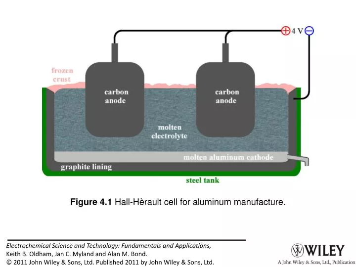
Figure 4.1 Hall-Hèrault cell for aluminum manufacture.

E N D
Figure 4.2 A chloralkali membrane cell. The multiplate cathode and anode are louvered as shown to deflect gas bubbles away from the membrane. The bubbles of hydrogen and chlorine become entrained in their respective solution streams, from which they are subsequently separated. Some of the sodium hydroxide produced in the electrolysis is diluted and recycled.
Figure 4.3 The electrolysis of water produces oxygen at the anode and hydrogen at the cathode. Ions from an electrolyte are necessary to provide conductivity but these play no role in the electrode reactions.
Figure 4.4 In electrodialysis, multiple membranes, alternatingly anion permeableand, cation permeable, direct the ions into the salt compartments, denuding the chambers they leave.
Figure 4.5 Three salt-splitting cell configurations applied to sodium sulfate solutions.
Figure 4.6 Salt-splitting cell incorporating bipolar and monopolar membranes. The letters represent Salt, Water, Acid, and Base.